16
Installation
3
Y
Y
G
G
C
C
W
W
Y
Y
G
G
C
C
W
W
Rc
Rh
W
C
G
Y
Y2
Y2
G2
G2
Rh
Rh
Rc
Rc
Y2
Y2
G2
G2
Rh
Rh
Rc
Rc
Rc
Rh
W
C
G
Y
Push any excess wire into wall and against mounting 9.
base. Seal hole in wall to prevent air leaks. Leaks can
aect operation.
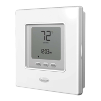
Snap case back together. Attach thermostat to back 10.
plate by inserting tab on bottom edge and hinging up
until top snap secures. See Fig. 4.
Close thermostat assembly making sure pins on back 11.
of circuit board align with sockets in connector.
Turn ON power to unit.
Turn ON power to unit.12.
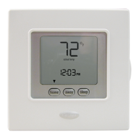
When power is applied, all display icons are lit for 2 seconds
to test the display.
Following this, unit conguration is displayed for an
additional 2 seconds:
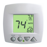
it will be heating + cooling (HP) or heating only (HO) or
cooling only (AC).
4
Attach NUI
a
b
Rc
Rh
W
C
G
Y
Rc
Rh
W
C
G
Y
English
 Loading...