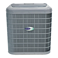
Air Conditioners and
Heat Pumps Using
R-22 Refrigerant
Application Guide
and Service Manual
NOTE: Read the entire instruction manual before starting the
installation.
This symbol → indicates a change since the last issue.
TABLE OF CONTENTS
SAFETY CONSIDERATIONS.....................................................2
INTRODUCTION..........................................................................2
INSTALLATION GUIDELINE ....................................................2
Residential New Construction..................................................2
Add-On Replacement (Retrofit)...............................................2
Seacoast (For Air Conditioners Only) .....................................2
ACCESSORY DESCRIPTIONS...................................................2
Compressor Crankcase Heater..................................................2
Evaporator Freeze Thermostat..................................................2
Winter Start Control .................................................................2
Compressor Start Assist—PTC ................................................2
Compressor Start Assist—Capacitor/Relay..............................2
Low-Ambient Controller ..........................................................2
MotorMaster™ Control ............................................................2
Low-Ambient Pressure Switch.................................................2
Wind Baffle...............................................................................3
Coastal Filter.............................................................................3
Support Feet..............................................................................3
Liquid-Line Solenoid Valve.....................................................3
Thermostatic-Expansion Valve.................................................3
Isolation Relay ..........................................................................3
LOW-AMBIENT GUIDELINE.....................................................3
LONG-LINE GUIDELINE............................................................3
Approved Systems ....................................................................3
Interconnecting Tubing Sizing .................................................3
Metering Device Sizing............................................................5
Liquid-Line Solenoid And Tubing Configuration...................5
Charging Information................................................................6
2–Speed Applications ...............................................................7
UNIT IDENTIFICATION .............................................................9
Product Number Stamped on Unit-Rating Plate......................9
Serial Number Identification ..................................................10
CABINET.....................................................................................10
Remove Top Cover-WeatherMaker™ ...................................10
Remove Fan-Motor Assembly-WeatherMaker™ ..................10
Information Plate—WeatherMaker™.....................................11
Control-Box Cover—Cube Products......................................11
Remove Top Cover—Cube Products.....................................11
Remove Fan-Motor Assembly—Cube Products....................11
ELECTRICAL..............................................................................12
Aluminum Wire ......................................................................12
Contactors................................................................................13
Capacitors................................................................................14
Cycle Protector........................................................................16
Crankcase Heater ....................................................................16
Time-Delay Relay...................................................................17
Pressure Switches....................................................................18
Defrost Thermostats................................................................18
Defrost-Control Board ............................................................18
Fan Motors..............................................................................22
Service Alarm Control Board.................................................23
Outdoor Thermostat(s)............................................................24
Compressor Plug.....................................................................24
Low-Voltage Terminals..........................................................24
RECIPROCATING COMPRESSOR ..........................................25
Mechanical Failures................................................................25
Electrical Failures ...................................................................26
System Cleanup After Burnout ..............................................27
Compressor Removal And Replacement ...............................28
COPELAND SCROLL COMPRESSOR ....................................28
Features ...................................................................................28
Troubleshooting ......................................................................28
Discharge Thermostat.............................................................28
Discharge Solenoid Valve ......................................................29
MILLENNIUM SCROLL COMPRESSOR................................29
Features ...................................................................................29
Compressor Protection............................................................29
Troubleshooting ......................................................................29
Scroll-Compressor, 3–Phase Monitor.....................................29
OLYMPIA SERIES HORIZONTAL UNITS.............................29
General ....................................................................................29
Remove Fan Motor.................................................................31
Cleaning Coil ..........................................................................31
TWO-SPEED SYSTEM ..............................................................31
Cautions and Warnings...........................................................31
System Functions....................................................................31
Factory Defaults......................................................................34
Major Components..................................................................34
LED Function/Malfunction Lights.........................................36
Troubleshooting ......................................................................36
REFRIGERATION SYSTEM .....................................................38
Refrigeration Cycle.................................................................38
Leak Detection........................................................................38
Brazing ....................................................................................39
Service Valves ........................................................................39
AccuRater™ (Bypass-Type) Heat Pumps Only ....................40
Reversing Valve......................................................................41
Thermostatic-Expansion Valves (TXV).................................42
Thermostatic-Expansion Valve (Bi-Flow TXV)....................43
Coil Removal ..........................................................................43
Liquid-Line Strainer (Heat Pumps Only) ..............................43
Accumulator............................................................................43
Contaminant Removal ............................................................45
System Charging.....................................................................45
Checking Charge.....................................................................45
CARE AND MAINTENANCE...................................................46
Visit www.carrier.com
Manufacturer reserves the right to discontinue, or change at any time, specifications or designs without notice and without incurring obligations.
Book 1144
Tab 3a 5a 2a 5a
PC 101 Catalog No. 563-732 Printed in U.S.A. Form 38-10SM Pg 1 11-00 Replaces: 38-1SM, 38-16XA




 Loading...