6 - SETTING UP TOUCH PILOT CONTROL
6.1 - General description
Touch Pilot includes the 7 in. touch screen allowing for easy system
control. Navigation through the Touch Pilot control is either using
the touch screen interface or by connecting to the web interface.
The navigation menus are the same for both connection methods
(Touch Pilot user interface and web browser). It is recommended
to use a stylus pen for the navigation via the touch screen.
NOTE: Some functions are unavailable when using the web
browser interface.
The Touch Pilot interface includes the following screens:
- Welcome screen
- Synoptic screen
- Operating mode selection screen
- Data/conguration screens
- Password entry and language selection screen
- Alarms screen
- Parameter modication screen
6.2 - Welcome screen
The Welcome screen is the rst screen shown after starting the
user interface. It displays the application name as well as the
current software version number.
To exit the Welcome screen and go to the Home screen
(see section 6.3), press the Home button.
Legend
1. Home button
2. Software version number
3. Information message box
Information message box: The information displayed in the status
bar at the bottom of the screen includes relevant messages
regarding the current user action.
Message Status
COMMUNICATION
FAILURE!
Equipment controller did not respond while
reading the table content.
ACCESS DENIED!
Equipment controller denies access to one of
the tables.
LIMIT EXCEEDED! The value entered exceeds the parameter limit.
Save changes?
Modications have been made. The exit must
be conrmed by pressing "Save" or "Cancel".
HIGHER FORCE IN
EFFECT!
Equipment controller rejects Force or Auto
command.
Too many users
connected ! Please
try again later ...
Too many users connected at the same time
(WEB INTERFACE ONLY)
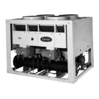
6.3 - Synoptic screen
The Synoptic screen allows you to monitor the vapour-refrigeration
cycle. The diagram indicates the current status of the unit, giving
information on the unit capacity, the status of water heat exchanger
pumps, and the pre-dened setpoint parameter.
All unit functions can be accessed by pressing the Main menu
button.
Example: Synoptic view. This picture is for information only.
It may differ from the actual look, depending on pumps and OAT sensor availability.
Legend
1. Home button
2. Main menu button
3. Login button (restricted access to menus)
4. Start/Stop button
5. Alarm button
6. Compressor + unit capacity
7. LWT and EWT (condenser)
8. Setpoint
9. Unit running status
10. LWT and EWT (evaporator)
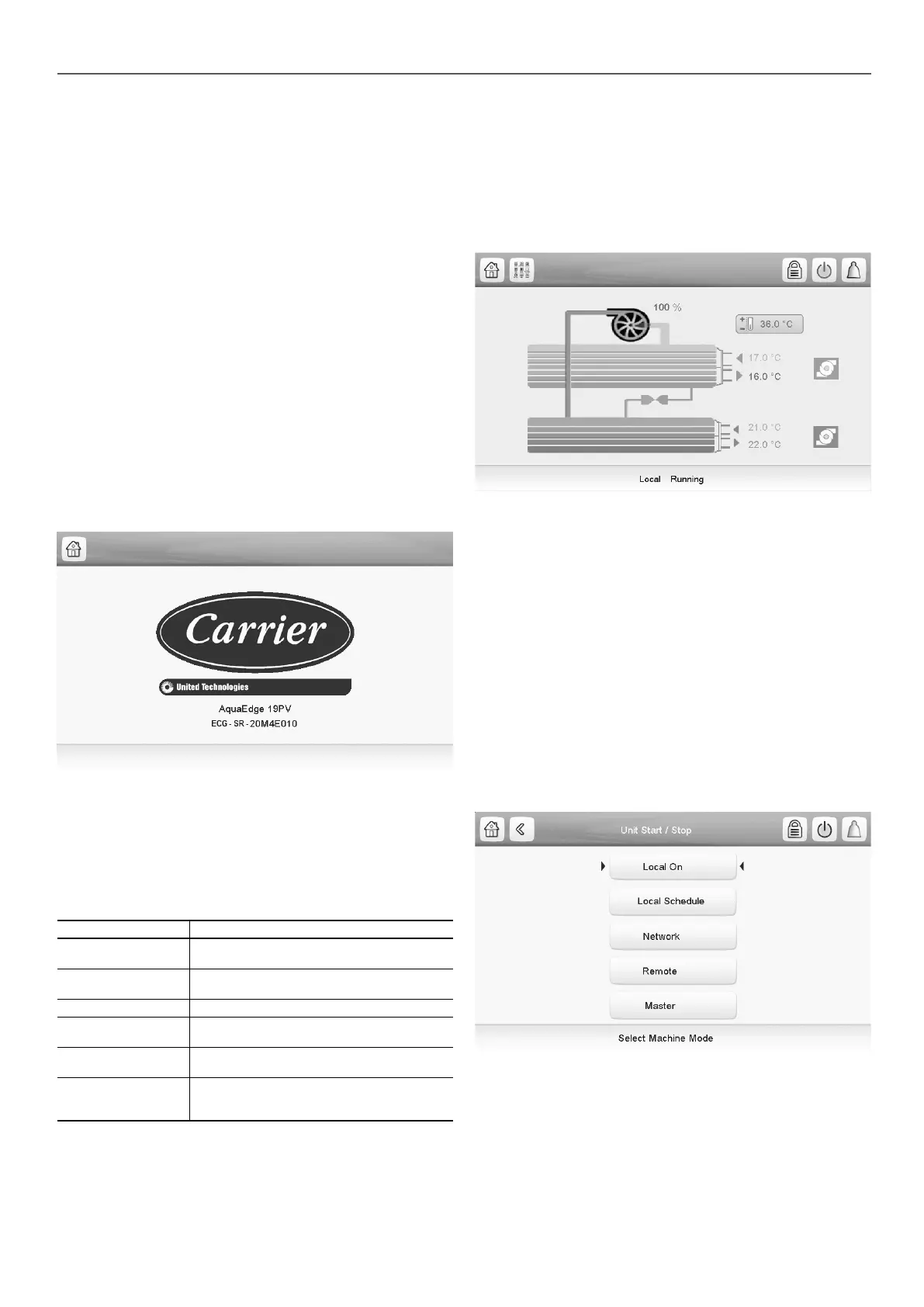
6.4 - Unit start/stop
With the unit in the Local off mode:
• To display the list of operating modes and select the required
mode, press the Start/Stop button in the upper-right corner
of the Synoptic screen.
IMPORTANT: When entering the menu, please note that the
currently selected item corresponds to the last running
operating mode.
B
C
D
G
C
B
D
E
F
H
I
J
K
11

 Loading...