% Building load
Reset value
8 - STANDARD CONTROL OPERATIONS AND OPTIONS
8.4.2 - Reset
Reset means that the active control point is modied so that the
machine capacity required is adjusted to be as close as possible
to the demand.
The reset source can be provided by one of the following:
■ Outdoor air temperature that gives a measure of the load
trends for the building. This reset source is applicable only to
units with option 154 (see section 8.15).
■ Return water temperature (heat exchanger ΔT gives an
average building load). Delta T (ΔT) is the difference between
leaving and entering uid temperatures (LWT minus EWT).
When the load is light, temperature difference across the
exchanger will be relatively small. The reset value should be
configured by the user and its configuration may differ
depending on the size of the water exchanger.
■ 4-20 mA reset signal provided by an active sensor connected
to the input: If the reading of the 4-20 mA signal/external
temperature value increases (load is lighter), then the current
setpoint will be lowered.
■ Space temperature reset based on the space temperature
sensor reading.
The source of the reset can be congured in the Reset Conguration
menu (RESETCFG). In response to a change in delta T, 4-20 mA
reset signal reading, or space temperature, the control point is
reset to optimise unit performance.
To set the source of the reset
1. Navigate to the Conguration menu.
2. Select Reset Conguration (RESETCFG).
3. Set Cooling Reset Select [cr_sel] or Heating Reset Select
[hr_sel].
Cooling Reset Select [cr_sel]
Heating Reset Select [hr_sel]
0 = none
1 = OAT *
2 = delta T
3 = 4-20 mA
4 = Space Temp
* OAT reset applies to units with option 154 (see section 8.15).
The unit normally uses two control point reset types, cooling control
point reset or heating control point reset.
Dry cooler condenser option has condensing setpoint reset which
can be applied if the condensing setpoint control depends on
outdoor air temperature reading (reset source = OAT). See also
section 8.15.
Reset is a linear interpolation function based on the following
three parameters:
■ A reference at which reset is zero (OAT / delta T / 4-20 mA
signal / space temp. – no reset value).
■ A reference at which reset is maximum (OAT / delta T / 4-20 mA
signal / space temp. – full reset value).
■ The maximum possible reset value: The difference between
the lowest reset value (no reset value) and the highest possible
reset value (full reset value). Cooling / Heating Reset Deg.
Value represents the maximum possible reset.
Reset parameters, i.e. slope, reset, and maximum value, are
congurable in the Reset Conguration menu (RESETCFG).
Cooling mode: Cooling control point reset is used to control the
evaporator water temperature reset.
Heating mode: Heating control point reset is used to control the
condenser water temperature reset.
Heating reset may be used to reset the condensing setpoint for
optimised condenser operation. This is only possible on the outside
temperature. Delta T is not used.
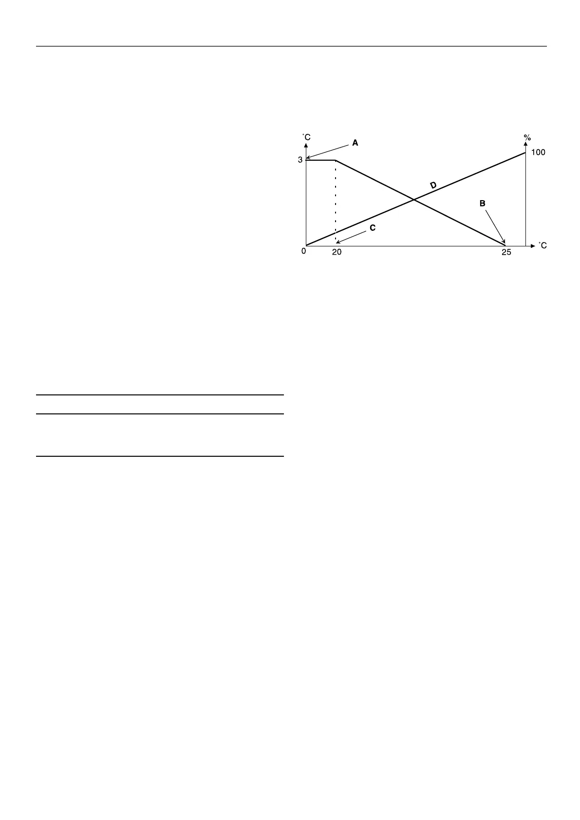
Reset example in Cooling mode for the space temperature
Legend
A: Maximum reset value
B: Space temperature for zero reset
C: Space temperature for maximum reset
D: Building load
8.5 - Ramp loading
The control provides the ramp loading function used to minimise
the rate at which the water temperature changes. The minimum
speed is calculated based on saturated condensing temperature
and saturated suction temperature. Ramp loading sequence can
be enabled by the user (Ramp Loading Select, GEN_CONF –
General Conguration).
8.6 - Capacity control
The unit is tted with oil-free centrifugal compressors with magnetic
bearings. Each circuit may have one or two compressors installed.
Compressors are controlled in such a way in order to provide the
best possible COP. Variable-speed centrifugal compressors exhibit
better performance at part load conditions; therefore, the control
system would normally start both circuits as soon as needed.
The Touch Pilot control adjusts the compressor capacity to keep
the heat exchanger water temperature at its setpoint.
8.7 - Demand limit
The demand limit functionality is used to limit the unit power
consumption whenever possible.
The control allows limitation of the unit capacity:
■ By means of user-controlled volt-free contacts: The unit capacity
can never exceed the limit setpoint activated by these contacts.
The limit setpoints can be modied in the SETPOINT menu.
■ By setting DEM_LIM when the unit is in Network mode.
■ By lag limit set by the master unit (master/slave assembly).
If the unit is not in the Master/Slave assembly, the lag limit value
is equal to 100%.
■ By night capacity limitation. The limit can be modied in the
GEN_CONF menu.
Capacity limitation is expressed in percentage, where a limit value
of 100% means that the unit may run with its full capacity (no
limitation is implemented).
27

 Loading...