2–1 62-11637
SECTION 2
UNIT DESCRIPTION
2.1 INTRODUCTION
WARNING
!
APX control system equipped units may
start automatically at any time the
START/ RUN-OFF switch (SROS) is in the
START/ RUN position. Also, the unit may
be fitted with two way communication
equipment that will allow starting of the
unit from a remote location even though
the switch is in the OFF position.
WARNING
!
When performing service or maintenance
procedures: ensure any two way commu-
nication is disabled in accordance with
the manufacturer’s instruction, ensure
the START/RUN-OFF switch is in OFF
position and, whenever practical, discon-
nect the negative battery connection.
This manual contains operating data, electrical data
and service instructions for the refrigeration units listed
in Table 2–1.
Additional support manuals are listed in Table 2–2.
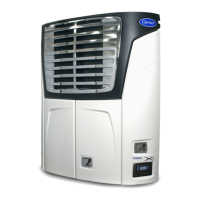
The unit model/serial number plate is located inside the
unit on the frame as shown in Figure 2.1.
2.2 GENERAL DESCRIPTION
The units described in this manual are one piece, self
contained, fully charged, pre-wired, refrigeration/heat-
ing “nosemount” diesel powered units. The units are
used on insulated refrigerated compartments to main-
tain cargo temperatures within very close limits.
The control system includes a manual switch, control
modules, fuses, and associated wiring. The unit may
be equipped with an optional remote light bar which
mounts separately on the front outside corner of the
compartment.
Temperature control is provided by the Carrier Transi-
cold APX
TM
control system (Refer to Section 2.5).
Once the system is set at the desired temperature, the
unit will operate automatically to maintain the desired
temperature within very close limits. The control sys-
tem automatically selects high and low speed cooling
or high and low speed heating as necessary to main-
tain the desired temperature within the refrigerated
compartment.
Standard equipment includes an auto start-stop fea-
ture. This feature provides automatic cycling of the die-
sel engine, which in turn offers an energy efficient
alternative to continuous operation of the engine with
control of temperature by alternate cooling and heating
of the supply air (evaporator outlet air).
The unit may be equipped with the AutoFresh
TM
Air
Exchange which controls air quality and humidity for
fresh produce.
The unit can be described as having three major sec-
tions:
• the condensing section (Figure 2.1 & Figure
2.2), which includes the unidrive and power train
(Figure 2.2).
• the evaporator section (Figure 2.3).
• the control system (Items 10, 11, 15, 27 & 28;
Figure 2.2 & Figure 2.7).
Table 2–1 Model Chart
Model R-404A Compressor Engine Engine Speed
X4 7300 NDW136 15 lb; 6.80 kg
05G 41cfm V2203L-DI-EF01e
High 1800
Low 1350
X4 7500 NDW236 16 lb; 7.26 kg
Table 2–2 Additional Support Manuals
Manual Number Type of Manual
62-11369 Parts Look Up System (PLUS)
62-11644 Operator’s Manual
62-11643 Easy To Run
62-11052 05G Compressor Workshop Manual

 Loading...