Do you have a question about the Carrier X4 7300 and is the answer not in the manual?
General safety guidelines for installation and servicing, emphasizing caution with moving parts and electrical components.
Explains hazard symbols (Danger, Warning, Caution, Notice) and specific safety directives for unit operation and maintenance.
Displays various safety decals with warnings and precautions in multiple languages.
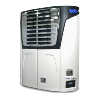
Describes the unit as a self-contained, nosemount diesel-powered refrigeration/heating unit for insulated compartments.
Details the components of the condensing section, including the engine, power train, and associated systems.
Explains the function and operation of engine control components like FSA, ENSSN, RPS, ENOPS, and ENCT.
Describes the evaporator section, its components, and its role in cooling the refrigerated compartment.
Details the function of the EVXV in controlling refrigerant flow and maintaining superheat.
Covers the APX control system, its features, and component descriptions and locations.
Lists and describes key APX control system components like PCM, MM, SVM, ENCU, and DM.
Provides electrical specifications for various unit components, useful for troubleshooting.
Explains the safety devices that protect the system from high pressure and unsafe operating conditions.
Details the operation of the vapor compression refrigeration system during cooling.
Explains the refrigerant flow and operation during heating and defrost cycles.
Describes the APX control system's LCD display interface, including its layout and key functions.
Provides step-by-step instructions for starting the refrigeration unit, including safety warnings.
Explains the IntelliSet feature for pre-selecting and managing unit settings for different products.
Details the Pretrip function, a series of tests to verify unit operation before loading cargo.
Guides the user on how to adjust the temperature setpoint using the control panel keys.
Explains how the Start-Stop feature reduces fuel consumption by cycling the engine based on conditions.
Describes the Continuous Operation mode, where the unit runs except for shutdown alarms.
Covers the built-in DataLink data recorder, its capabilities, and data management.
Details the process for downloading recorded data using TRU-Tech or a USB memory device.
Explains how to manually initiate a defrost cycle when conditions are met.
Describes how to access and use the Advanced User Mode for additional data and menu options.
Explains how to access and view various unit data points and system information.
Guides the user on how to view and interpret active alarms displayed on the system.
Covers the various functional parameters that can be configured to customize unit operation.
Provides instructions on how to properly shut down the refrigeration unit.
Details the electrical sequence of operations from battery connection to module communication.
Explains how the engine is controlled, including start-up sequences and speed adjustments.
Describes the automated process for starting the engine, including preheat and cranking.
Outlines the various operating modes of the refrigeration system, such as cooling, heating, and defrost.
Details the control system's operation during cooling mode, including component actions.
Details the control system's operation during heating mode, including component actions.
Explains the UltraFresh temperature control for perishable and frozen ranges.
Refers to Section 4.9 for a description of the defrost cycle operation.
Explains how the system determines and maintains compartment temperature.
Describes how temperature readings from specific sensors are used for control.
Explains the Start-Stop feature for fuel efficiency and temperature control.
Details how Start-Stop operation depends on Configuration and Functional Parameter settings.
Lists the five criteria that must be met for the unit to stop in Start-Stop Operation.
Outlines the conditions under which the unit will restart during an OFF cycle.
Describes Continuous Operation, typically used for fresh produce, where the unit runs except for shutdown alarms.
Explains the defrost cycle, its initiation, and operation.
Covers how defrost can be started manually or automatically based on conditions.
Details four optional software override programs for enhanced operation and product protection.
Explains the FreshProtect feature for flexible supply air temperature limits.
Describes how to lock the unit into Start-Stop or Continuous Operation based on setpoint ranges.
Details ProductShield configurations for improved operating efficiency and product protection.
Lists and explains various software overrides that can alter unit operation.
Explains Cargo Protect Mode activation when return and supply air sensors are simultaneously inactive.
Explains engine speed override parameters based on various conditions.
Lists factors that determine unloader operation in addition to temperature control.
Details CSMV control overrides based on engine parameters and system pressures.
Outlines the four methods for interacting with the APX control system.
Describes Technician Mode access for viewing alarms, hour meters, configurations, and performing tests.
Explains how to view additional hour meters available in Technician Mode.
Details the two sections of the Alarm list (active and inactive) and how alarms are managed.
Explains how configuration settings match the system to the unit and define operational actions.
Describes Component Test Mode for energizing individual circuits for testing.
Explains when Service Mode must be used, such as for refrigerant removal or leak checking.
Provides instructions for using USB memory devices for data transfer, software installation, and configuration.
Details the creation and use of a USB device for transferring data and software.
Explains PC Mode for accessing the system without the engine running for demonstrations and changes.
Guides the user on downloading data from the DataLink recorder to a USB device.
Provides instructions for installing software from a USB memory device into the control system.
Details how to install configuration files from a USB device into the control system.
Covers the TRU-Tech & TRU-View software for accessing and downloading data.
Explains the functions of the TRU-Tech program for monitoring, recording, and editing system data.
Describes the TRU-View program's capabilities for reading and analyzing system data with customized reports.
Provides instructions for connecting a computer to the control system using a USB service cable.
Covers the procedure for replacing the main microprocessor module, including necessary data and software.
Outlines essential unit-specific and time-sensitive data that must be known before microprocessor replacement.
Details the physical process of replacing the main microprocessor module.
Explains the configuration steps required after installing a replacement microprocessor.
Details the final checks and Pretrip test after servicing to ensure proper unit operation.
Provides guidance for troubleshooting alarms and reviewing active and inactive alarm lists.
Lists and describes various unit alarms, including activation conditions, unit control, and reset.
Lists and details troubleshooting steps for engine-related alarms.
Covers troubleshooting for refrigeration system and temperature control related alarms.
Details troubleshooting for alarms related to electrical components and communication.
Covers alarms related to datalogger, door status, sensor inputs, and communication errors.
Provides an overview of the Service section's presentation of procedures.
Outlines regular maintenance requirements for optimal unit operation and longevity.
Details the pre-trip inspection procedures to be performed before each trip and at maintenance intervals.
Covers procedures for servicing external components like fresh air exchange, grille, and doors.
Details the process for removing the grille insert for access and service.
Explains how to maintain and replace door latch assemblies for smooth operation.
Covers servicing procedures for the engine, fuel system, cooling system, and air cleaner.
Describes the components of the fuel system and its two configurations.
Provides step-by-step instructions for priming the fuel system, especially after running dry.
Details the procedure for replacing the spin-on fuel filter element.
Explains how to replace the suction side fuel filter.
Covers the procedures for checking and changing engine oil and the oil filter.
Details the inspection and maintenance of the air cleaner for engine performance.
Outlines procedures for cleaning and flushing the cooling system and refilling coolant.
Covers the inspection, replacement, and tensioning of the water pump/alternator belt.
Provides service instructions for the power train system, including belts, gearbox, and fanshaft.
Details the procedure for removing and reinstalling the lower belt.
Explains how to remove and reinstall the upper belt.
Provides instructions for removing and reinstalling the clutch assembly.
Details the procedure for removing and reinstalling the evaporator fan.
Covers procedures for servicing the refrigerant system, including charge, leak checking, and evacuation.
Details methods for checking, removing, and adding refrigerant charge to the system.
Explains procedures for leak checking the refrigerant system under various conditions.
Outlines the process for evacuating and dehydrating the refrigeration system to remove moisture.
Provides procedures for servicing the compressor and its unloaders.
Guides on checking conditions to determine if compressor repair or replacement is necessary.
Details the step-by-step process for removing and replacing the compressor.
Covers the service procedures for the compressor's cylinder head and valve plate components.
Explains the service procedures for the compressor's oil pump and bearing head assembly.
Details how to check and add oil to the compressor while it is installed in the system.
Provides procedures for checking unloader operation and replacing unloader coils.
Covers service for individual refrigerant system parts.
Explains how to clean the evaporator coil to maintain airflow and unit capacity.
Details cleaning procedures for the condenser coil and replacement of the assembly.
Covers checking the filter-drier for restriction and replacement procedures.
Provides checkout procedures for SV1 and steps for replacing its coil or internal components.
Details procedures for replacing the coil or internal components of SV2 and SV4 solenoid valves.
Explains the CSMV's purpose and provides diagnostic steps for malfunction.
Details diagnostics and replacement procedures for the EVXV, noting it rarely requires maintenance.
Covers replacement and checking procedures for the high pressure switch.
Explains how to test transducer wiring and provides comparison notes for Unit Data readings.
Details testing procedures for the defrost air switch using a magnehelic gauge and ohmmeter.
Covers servicing procedures for key electrical system components.
Refers to Section 5.5.2 for complete replacement instructions for the main microprocessor.
Provides instructions for disconnecting power leads and removing/replacing the Power Control Module.
Covers the procedure for servicing the display module, including replacement and software compatibility.
Provides a caution regarding battery polarity and instructions for inspection and brush replacement.
Explains how to check sensor resistance values using an ohmmeter and test equipment.
Provides troubleshooting guidance for various engine indications and troubles.
Lists possible causes and actions for an engine that will not crank or start.
Covers troubleshooting for starter motor issues, including cranking problems and engagement failures.
Addresses troubleshooting for various refrigeration and temperature control problems.
Lists possible causes and actions when the unit fails to cool.
Covers issues related to the defrost cycle not initiating, manually initiating, or not terminating.
Illustrates and lists component-to-terminal assignments for PCM, 1MM, 2MM, and 3MM connectors.
Lists splice point numbers and their corresponding component connections for wiring analysis.
Refers to the subsequent page for the complete wiring schematic of the unit's electrical system.
| Brand | Carrier |
|---|---|
| Model | X4 7300 |
| Category | Utility Vehicle |
| Language | English |