SC-409-10 Installation and Operating Instructions Page 7 of 16
CP4958A 11/10/05
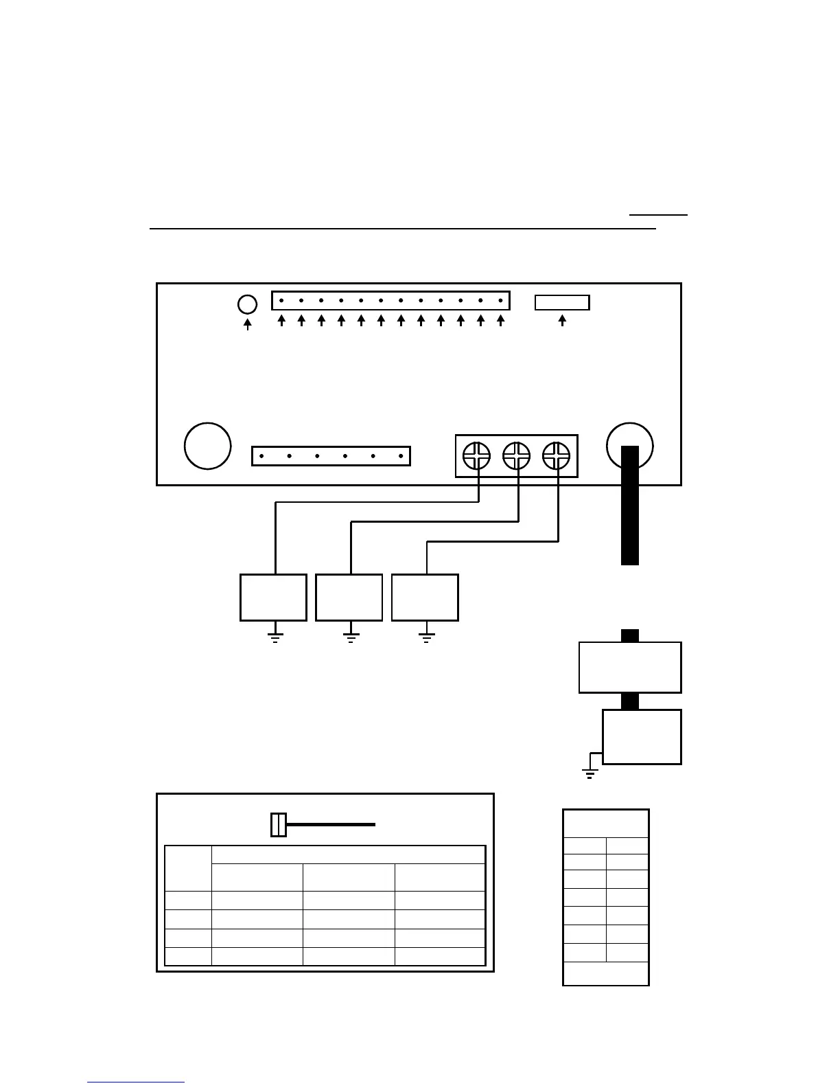
LIGHT CONTROL CONNECTIONS
The power inputs for the light controls are separate from the power input for siren. Also the power
inputs for the lever switch and six auxiliary control switches are separate. This helps prevent a
fault in one main circuit from affecting another main circuit.
Fuses / Breakers
Each light control output is fused and should be limited to 20 Amps. Properly rated circuit break-
ers should be connected between the power source and light control power inputs. Failure to
install proper circuit breakers or fuses can result in damage to the unit and/or vehicle.
Lever Switch Connections
Recommended
Wire Size
Amps Size
5 - 10 #16
10 - 15 #14
15 - 25 #12
25 - 40 #10
40 - 60 #8
60 - 80 #6
Use next larger size
if longer than 10 ft.
Outputs Turned On
Option NPL Off
(Default)
Option NPL On
Option NPO Off
Option NPL On
Option NPO On
Off All off
1 Load LV1 only Load LV1 only Load LV1 only
2 Loads LV1, 2 Load LV2 only Load LV2 only
3 Loads LV1, 2, 3 Load LV3 only Loads LV1, 2, 3
Lever
Position
Off 1 2 3
BAT
-
+
Supplied with #10 AWG RED
Internal screw pressure terminal
will accept up to #6 AWG for input
current higher than 40 Amps
Circuit Breaker
Limit input up to
60 Amps Max.
NEG
NEG
VID
ENA
AUX
RAD
RAD
CUT
POS
POS
SPK
SPK
RAD
VOL
SIREN
FUSE
SW6
SW5
SW4
SW3
SW2
SW1
LV3
LV2
LV1
Load LV1
20 Amps
Max.
Load LV2
20 Amps
Max.
Load LV3
20 Amps
Max.
25A Automotive Type Fuses
for outputs on bottom of unit
NOTE: THE NEGATIVE (NEG) CONNECTIONS
ON 12-P PLUG ARE ALSO REQUIRED