SC-409-10 Installation and Operating Instructions Page 9 of 16
CP4958A 11/10/05
LEVER AND AUXILIARY CONTROL SWITCH PROGRAMMING
Each position of the lever switch and the six auxiliary control switches may now be programmed
once electrical connections are made and power is available to the unit. The programming mode
is entered by changing an internal DIP switch.
Note: The unit must be turned on and off with the switch on the enable input to program the func-
tion of each auxiliary control switch. See Unit Enable Input Connection under ELECTRICAL
CONNECTIONS section. The Instant On feature will only allow programming of the lever switch
positions when the lever switch is in 1, 2, or 3.
Note: Any lights and devices including Automatic Siren will operate like normal when the lever
switch positions change or the auxiliary control switches are activated. Temporarily disabling the
Automatic Siren or disconnecting speaker(s) while programming is recommended. See OPTION
SWITCHES section.
Follow these steps to program the unit.
Access the internal DIP switch.
1. Turn unit off (backlight LEDS and Auxiliary Control Switches dark)
2. Optionally detach the 6-P plug from the back of the unit to prevent activating lights and de-
vices while programming.
3. Detach the 12-P plug from the back of the unit to prevent shorting while removing cover.
4. Remove the case cover by removing two screws at the bottom rear corners of the unit.
5. Re-attach the 12-P plug onto the back of the unit.
Get into program mode.
1. Turn unit on with enable input or lever switch.
2. Enter the program mode by turning SWB-3 (PGM) DIP switch ON. Two beeps sound con-
firming the unit entered program mode. See OPTION SWITCHES section for location.
Set Auxiliary Control Switch Operation (Lever Switch in OFF Position).
1. With lever switch in off position, each auxiliary switches current operation program status is
indicated on the face of the unit using colors and flashing. See the table below for switch
status definition.
2. Change each switches operation by momentarily pushing the switch.
Note: The Timed Momentary operation, typically used as a Gun Lock Timer, must begin with
switch 6. If switch 6 is programmed as timed momentary only then may switch 5 be programmed
also as a timed momentary and so on.
Each lever switch position 1, 2, or 3 may be programmed to also automatically turn on any of the
auxiliary switch controls except Timed Momentary (Gun Lock Timer). These auxiliary switch con-
trols may still be operated manually even if they were turned on automatically. Each time the
lever switch changes position, the combined auxiliary switch controls are turned on or off. When
the lever switch is turned OFF, all of the auxiliary switch controls tied to a position(s) on the lever
switch are turned off while the other auxiliary switches are unaffected.
Programming continued on next page.
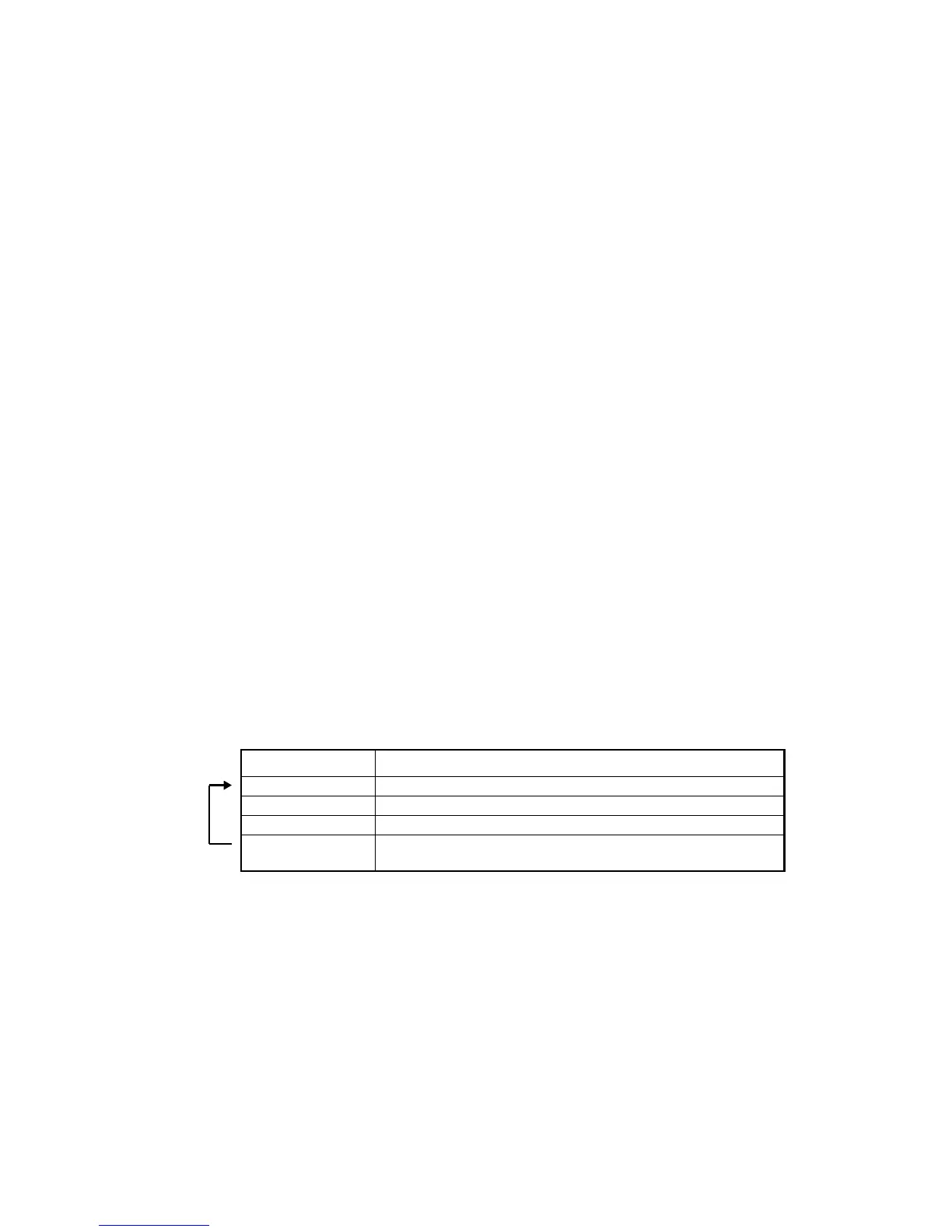
Switch Status Auxiliary Control Switch Operation
Constant RED Push On / Push Off and activate Video Trigger output (Default)
Constant GREEN Push On / Push Off
Flashing Momentary
Flashing 2X Rate
Timed Momentary (Gun Lock Timer)
(On for 10 seconds or 20 seconds See Timer option)
Loop