I-120
GH Pump 120 – 16.02.EN
10
D. LEVELING OF UNIT. When the pump is supplied
complete with motor and base, the unit is assembled at
the factory. Lower unit onto foundation, positioning base
structure so anchor bolts are aligned in middle of holes
in base.
The base should be supported on either rectangular
metal blocks with shims or on metal wedges having a
small taper. The support pieces should be placed close
to the foundation bolts. Refer to Figure 4, Grouting and
Foundation Bolting. Place supports directly under the
part of the base plate, which carries the greatest weight.
Space the supports closely enough to provide uniform
support of the base plate. Adjust the metal supports or
wedges until the shaft is level. Check suction and
discharge flanges of the pump by means of a level.
Make corrections, as necessary, by adjusting the
supports or wedges under the base plate.
The base should be supported on metal shims or metal
wedges placed directly beneath the part of the base
supporting the most weight. The shims or wedges
should be spaced close enough to give support and
stability.
Adjust metal supports or wedges until suction and
discharge flanges are level.
CAUTION
Do not attempt to straighten the base by using
the anchor bolts.
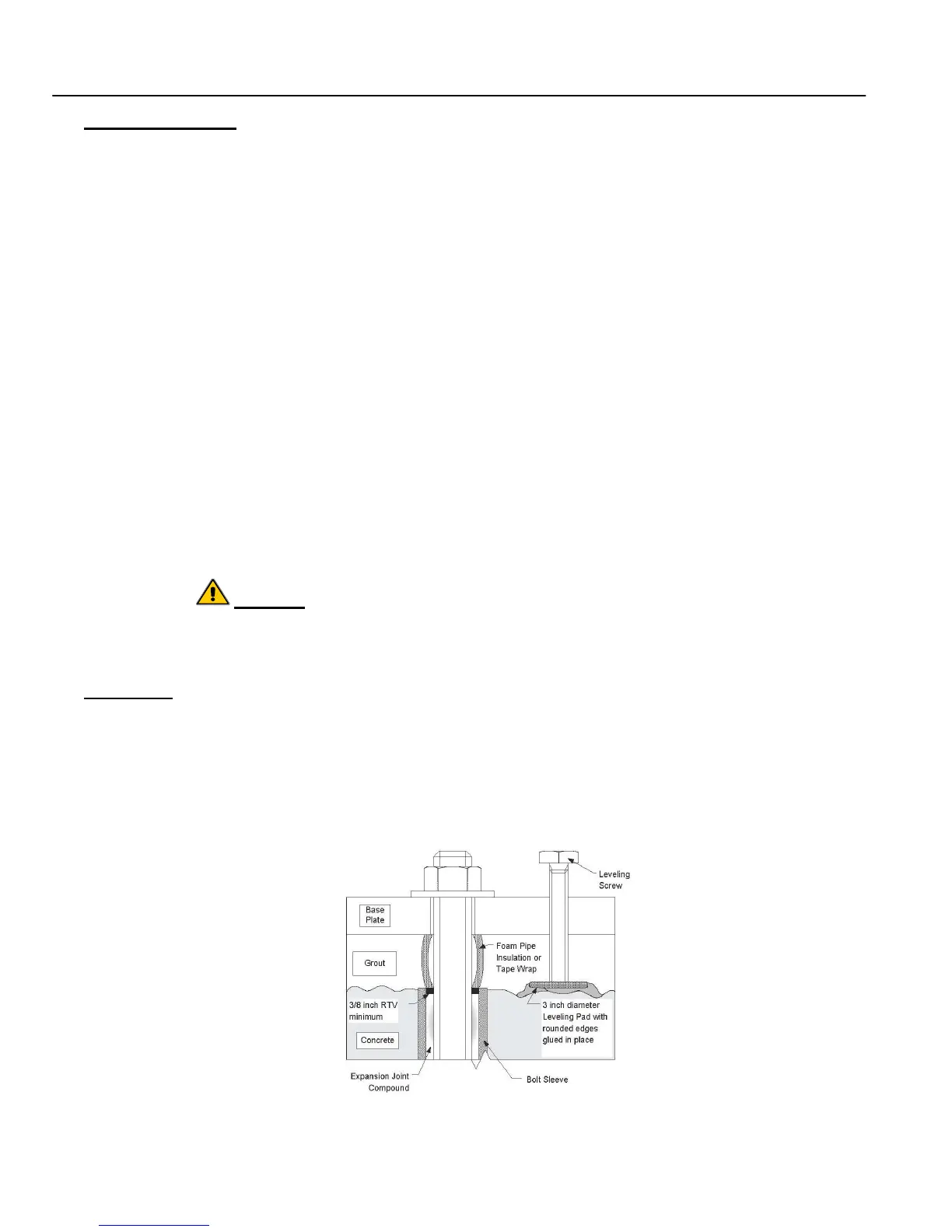
E. GROUTING. After the pumping unit has been
leveled and the alignment is correct, grout the unit to the
foundation using a high-grade, non-shrinking grout, refer
to Figure 4. Proceed grouting using the following
procedure:
Prepare concrete foundations, anchor bolts and leveling
screws according to individual instructions covering
these items.
1. Wax forms heavily with at least three coats of
paste wax. Forms must be substantial and well
braced. All corners, joints, bottoms must be
sealed with silicone caulk for water tightness. All
forms should have a 45° chamfer strip installed
to prevent stress risers.
2. Anchor bolt-free length must be wrapped with
duct seal or electricians plastic tape to prevent
grout from contacting the bare metal. Grout
sticking to the anchor bolt will prevent the
elongation necessary to develop the hold-down
force. Failure to do this will result in broken
anchor bolts.
3. If equipped leveling screws must be greased to
permit removal prior to the final torque.
4. Do not use shim packs as a leveling device
unless it is planned to remove them prior to final
torque application.
5. Leveling screw pads should be a minimum of
1/2" thick with minimum diameter of 3". Corners
of pad must be rounded to approximately 1/8"
radius to prevent stress cracking. Set leveling
screws on the chipped concrete surface. Set the
pad with quick set cement or resin repair
compound. With jacking bolt pads secure and
level, set and level base with leveling screws. If
not equipped with leveling screws use shims to
level.
6. The underside of the standard factory steel
base plate was painted with epoxy grout primer
and should only require proper cleaning. If the
base must be sandblasted, prepare the contact
faces to SSPC-SP 6 Spec. If base cannot be set
within 24 hours of blasting, the underside must
be coated with a compatible rust inhibitive
primer. Tighten foundation bolts loosely. Allow
the grout to fully cure before firmly
tightening the foundation bolts.
Figure 4. Grouting and Foundation Bolting