I-120
GH Pump 120 – 16.02.EN
26
14. Install remaining packing (180) as described in
Steps 8 through 10 above.
NOTE
In tightening the gland (17), gland hex nuts
(615) should be adjusted evenly to avoid
cocking the gland and subjecting the packing
(180) to uneven pressure.
15. Seat final ring of packing (180) firmly with the
gland (17) halves. Install the gland flat washers
(641) and gland hex nuts (615) on studs (630)
using a wrench to tighten.
16. Ensure that lantern ring (29) is still properly
aligned with the flush port.
17. Loosen gland hex nuts (615) and retighten,
using only fingers.
18. At minimum the gland (17) should be into the
stuffing box approximately 3 - 5mm (1/8” -
3/16").
19. The remaining exposed portion of gland (17)
follower should be at least 6mm (1/4”) to allow
future gland adjustments.
20. Rotate shaft (6) by hand to ensure shaft is not
binding.
21. Allow liberal leakage at start up.
22. Slowly adjust leakage to an acceptable level by
tightening gland hex nuts (615) slowly and
evenly. Final adjustments should be made by
rotating gland hex nuts one flat at a time.
NOTE
If stuffing box is hot to the touch (approximately
65°C or 150°F), there is not enough flush water
entering the stuffing box.
23. Packing (180) may run warm during break-in
period, one day or two.
24. Do not adjust the packing (180) unless
necessary.
25. If uncontrolled excessive leakage occurs,
lantern ring (29) is pushed out of alignment with
flush water port, or gland (17) follower cannot
be tightened further; re-pack the pump.
F. REPLACEMENT OF MECHANICAL SEAL. A
mechanical seal (90) must be installed and serviced
while the casing (1) is removed from the motor or
bearing frame (19) or intermediate (71).
Mechanical Seal Removal
NOTE
Refer to mechanical seal vendor instructions for
proper mechanical seal removal procedure.
Disassemble pump per Section XI, Paragraph B. steps 1
through 11. Take special care with the mechanical seal
(90) rotary and stationary elements when sliding the
casing (1) off of the shaft (6).
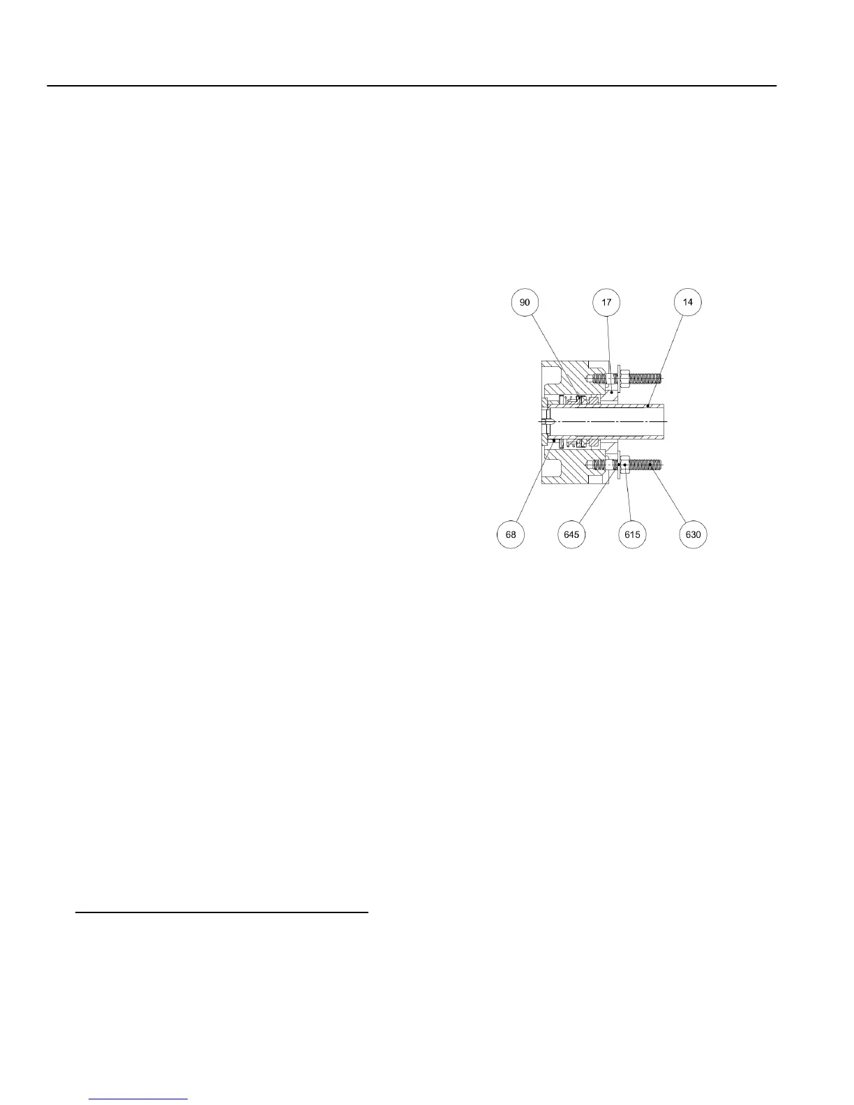
Figure 8. Mechanical Seal
Mechanical Seal Installation
1. Lubricate and install sleeve O-ring (89X) onto
shaft (6).
NOTE
For a cartridge seal, refer to mechanical seal
vendor instructions for proper seal installation
procedure.
2. If applicable, install cartridge mechanical seal
(90*). DO NOT remove seal clip until after pump
assembly is complete.
NOTE
Refer to mechanical seal vendor instructions for
complete seal installation procedure.
3. If stationary element of mechanical seal (90) is
to be replaced, clean, dry, and lubricate gland
(17). Lubricate stationary element of mechanical
seal with suitable lubricant. Insert stationary
element of mechanical seal into gland.