I-120
GH Pump 120 – 16.02.EN
25
and gland flat washers (645) .Install tubing and
tubing fittings, as applicable.
24. Check for smooth shaft rotation. Install splash
guard (*131A) in bearing frame (*19) or
intermediate (*71).
CAUTION
Use a hoist with adequate lifting capacity; refer
to Section VII, Paragraph B, for lifting the
pump.
25. Return pumping unit to installation site. Install
pumping unit on its base and secure to base
with foundation bolts.
26. On frame-mounted pumps, align coupling (*42)
in accordance with Section VII, Paragraph F.
Reconnect coupling. Install coupling guard
(*131).
27. Reconnect piping and gauges, as necessary.
Remove all tags from valves and switches.
Open system valves. Reconnect power supply
to motor.
28. Start pumping unit in accordance with section
IV, Operation.
E. REPLACEMENT OF PACKING. Pumps equipped
with packing have a lantern ring which is located in line
with the flush water connection on the stuffing box. Flow
should be adjusted, typically to 20 to 30 drops per
minute. Flush water pressure should be approximately
70 kPa (10 PSI) more than the pump discharge
pressure to ensure flow of water through the packing.
Use the following procedure when replacing the
packing:
1. Ensure the new packing is of proper type and
size.
a. Typical is five rings, 6mm x 6mm (3/8” x
3/8”).
b. Standard shaft diameter is 32mm (1 1/4”).
c. Pre-cut sets of packing and lantern rings
are available for stock from Carver Pump
Company
2. Stop the pumping unit; refer to Section VIII,
Paragraph E.
3. Carefully bleed off pressure and remove splash
guard (*131A).
4. Remove gland hex nuts (615) and the gland flat
washers (645) on studs (630). Slide back and
remove gland (17) halves.
CAUTION
Do not use system pressure to blow out
(remove) packing.
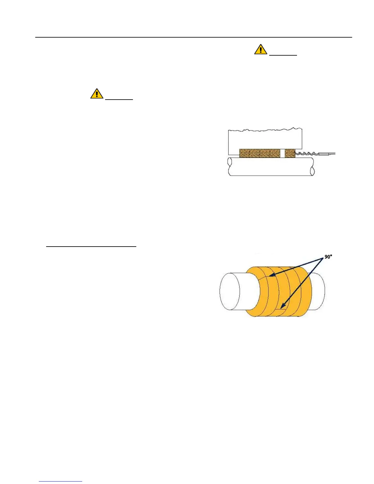
5. Refer to Figure 6; remove all old packing rings
(180) by using the proper size packing removal
hook. The lantern ring (29) will remain on the
shaft (6) and should be slid to near the slinger
(40).
Figure 6. Removing Packing with Hook
6. Check the shaft (6) for nicks and score marks;
repair or replace as necessary.
7. If required, clean the stuffing box bore.
8. Install the first ring of packing (180) with joint at
approximately the 1 o’clock position (30° right of
vertical). Refer to Figure 7 for packing
alignment.
Figure 7. Packing Alignment
9. Twist the ring of packing (180) slightly in an “S”
shape and place it around the shaft (6).
10. Seat packing (180) firmly against bottom of
stuffing box using the gland (17).
11. Repeat procedure as described in Steps 8
through 10. Packing (180) ring joints should be
staggered 90° apart.
12. Install enough rings (typically 2) until lantern ring
will align with flush water port.
13. Slide lantern ring (29) back up shaft (6) into
position.