Figure 14
Figure 15
- Remove tappet caps:
Loosen the four fixing screws (1) and lift the caps (2);
remove the gaskets.
- Disassemble su c t ion an d exhaust manifolds: loosen the
8 screws (1) fixing the suction manifold plate to the
cylinder head (two of them have already been
screwed−out sinc e fixing the pipe brackets to th e
injectors); from the exhaust manifold side;
loosen th e eight (2) fixing screws; remove the gaskets.
- Disassemble rocker arm bearings; loosen the two fixing
screws (2) and remove the complete rocker arm bearing;
withdraw tappet rods. Repeat the operation for all the
remaining roc ker ar m bearings.
- Disassemble water temperature transmitter (1).
!
In the picture, the front cap has already been
remo ved.
On the central cap there is a blow−by valve for the
lubrication oil vapours.
All the gaskets shall always be replaced durin g
assembly.
12
75681
2
1
75682
Figure 16
75683
1
2
Figure 17
75684
2
3
1
4
5
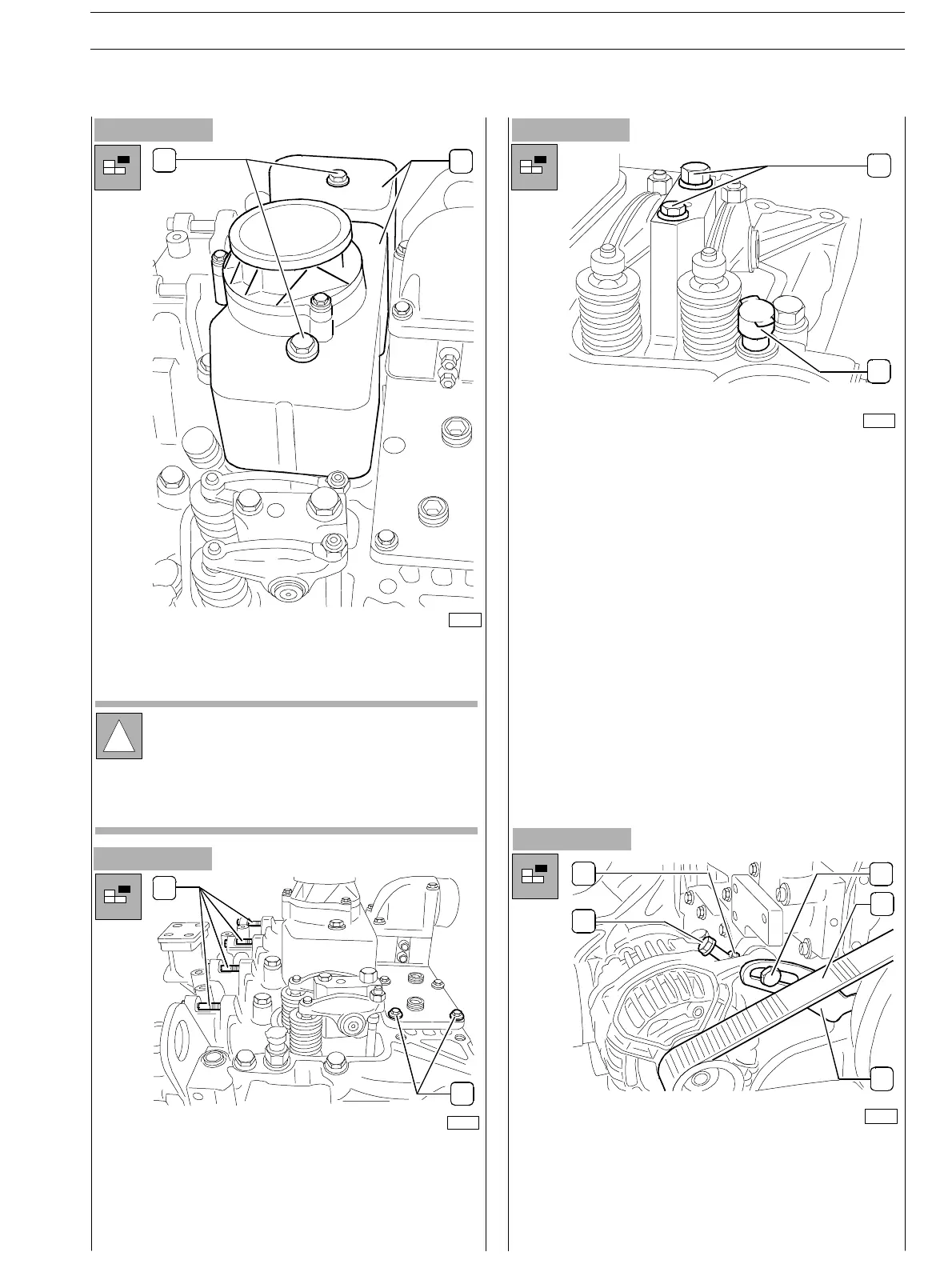
- Loosen the screw (1) on the alternator belt tensioning
hanger and by loosening the lock nut, loosen the screw
as well (3) in order to slack the belt (4) until enabling
withdrawal of th e driven and guide pulleys.
Disassemble alternator belt tensioning hanger (5).
SECTION 3 − DUTY − INDUSTRIAL APPLICATION E NG I NE S
13
ED. FEBUARY 2003
zs