Figure 18
Figure 19
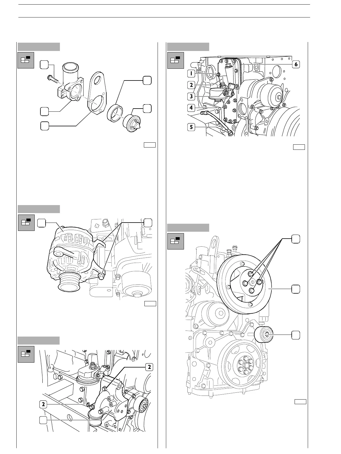
- Disassemble thermostat unit; loosen the three fixing
screws (1) and disassemble the t hermostat unit (2)
together with the bracket (3); remove the gasket (4) and
the thermostat (5).
- Assemble the bracket in th e original position fixing it with
the screws of the thermostat unit.
- Proper ly hold the alternator (1) separatin g it from its
bearing by loosening the screw (2); remove screw nut
and washer.
Figure 20
Figure 21
- From the front, disassemble transmission pulley (1).
- Loosen the four screws (2) and disassemble th e pulley
(3) from the bearing underneath.
- Proceed disassembling the bearing.
75685
1
2
3
4
5
1
2
75686
1
- Loosen the screws (2) and withdraw the alternator
bearing (1).
75810
- Loosen the screws (4) and disassemble the oil
pressure/temperature sensor (3) (if fitted).
- Loosen th e screws (1) an d disassemble the oil filter/heat
exchanger bearing (2), inter layer plate (6) and relating
gaskets.
- Disassemble oil level sensor (5) (whether provided).
- Disassemble injection pump (see specific procedure)
and the power take−off underneath.
Figure 22
1
3
2
75687
SECTION 3 − DUTY − INDUSTRIAL APPLICATION
14
E NG I NE S
ED. FEBUARY 2003
zs