Figure 23
Figure 24
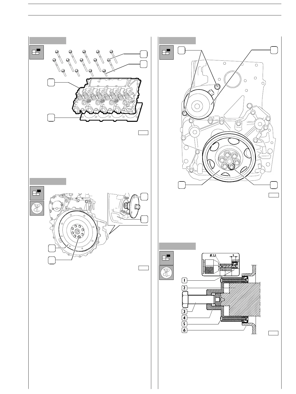
- Disassemble cylinder head;
loosen the screws (1) and (2) fixing the cylinder head (3);
hook the brackets with metal ropes and, throughout a
hoist withdraw c ylinder head from th e block.
-
Use the 380000988 tool (2) to operate on the flywheel
cover box (1) in order to block flywheel rotation (3).
(Utilise starter holding down stu ds and fixing screw
nuts).
- Loosen the flywheel fixing screws (4) to engine drive
shaft.
Figure 25
- Remove the engine drive shaft fixing rin g from t he front
c
over. Use the tool 380000665 (4) to operate on the front
tang (2) of the engine drive shaft. Throughout the tool
guide ports, drill the internal holding r ing (1) using Ø 3,5
mm drill for a 5mm depth. Fix the tool to the ring
tightening the 6 screws specially provided.
Proceed withdrawing the ring (1) tightening the screw
(3).
- Loosen the s crews (1) and withdraw water pump (2).
- Loosen the screws (3) and disassemble the pulley (4).
Figure 26
00900t
75688
3
4
1
2
75692
3
4
1
2
12
34
75689
SECTION 3 − DUTY − INDUSTRIAL APPLICATION E NG I NE S
15
ED. FEBUARY 2003
zs