Figure 180
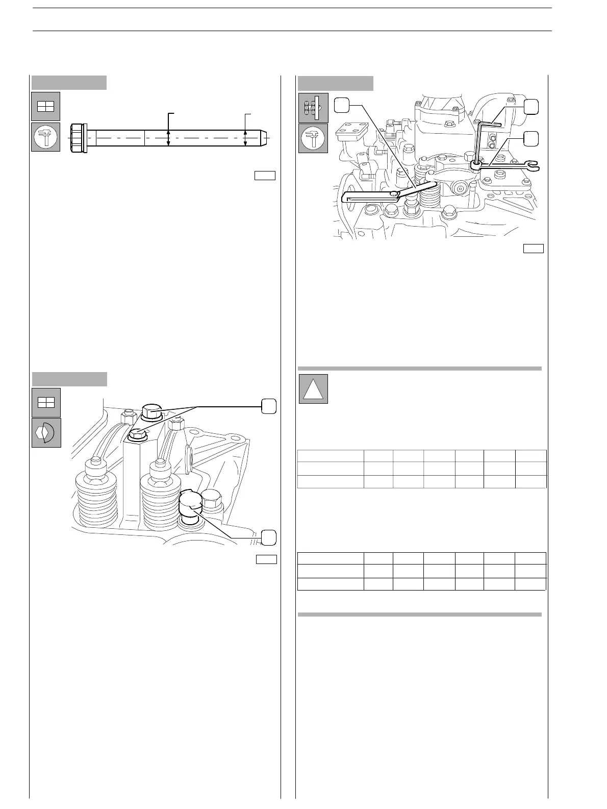
Figure 181
- Tighten the screws (2) to the prescribed couple and
assemble water temperature sen sor (1).
!
In order carry out a quicker adjustment of the
working slack between rocker arms and valves,
proceed as following:
Rotate the engine drive shaft, balance the valves of
cylin der 1 and adjust the valves identified by star
symbol, as indicated in the following table:
Adjust the slack between rocker arms and valves using socket
wrench (1), point wren ch (3) and feeler gauge (2).
Correct working slack is:
− suction valves 0.30 0.05 mm
− exhaust valves 0.55 0.05 mm.
Figure 182
D1D2
75703
- Insert the tappet driving rods and the Rocker Arm unit.
Before usin g the fixing screws again, measure them twice
as indicated in the picture, checking D1 and D2
diameters:
if D1 − D2 < 0,1 mm the screw can be utilised again;
if D1 − D2 > 0,1 mm the screw must be replaced;
1
2
75683
75806
2
1
3
Rotate th e engine drive shaft of 360 deg., balance the
valves of cy linder 6 and adjust the valves identified by
star sy mbol, as indicated in the following table:
Cylinder n.
Suction
Exhaust
1
234
*
*
*
*
*
−
−
−
56
−
−
Cylinder n.
Suction
Exhaust
1
234
−
− * −
−
−
*
*
56
*
*
*
−
*
−
SECTION 3 − DUTY − INDUSTRIAL APPLICATION
58
E NG I NE S
ED. FEBUARY 2003