Figure 176
Figure 177
Figure 178
SHAFT AND ROCKER ARM BASIC DATA
Check the coupling surfaces of bearing and shaft: no evidence
of excessive wear shall be detected or damages.
Replace if necessary.
- Carry out the assembly of the rocker arms after previous
check of the components.
Figure 179
75705
1
2
3
4
1
2
3
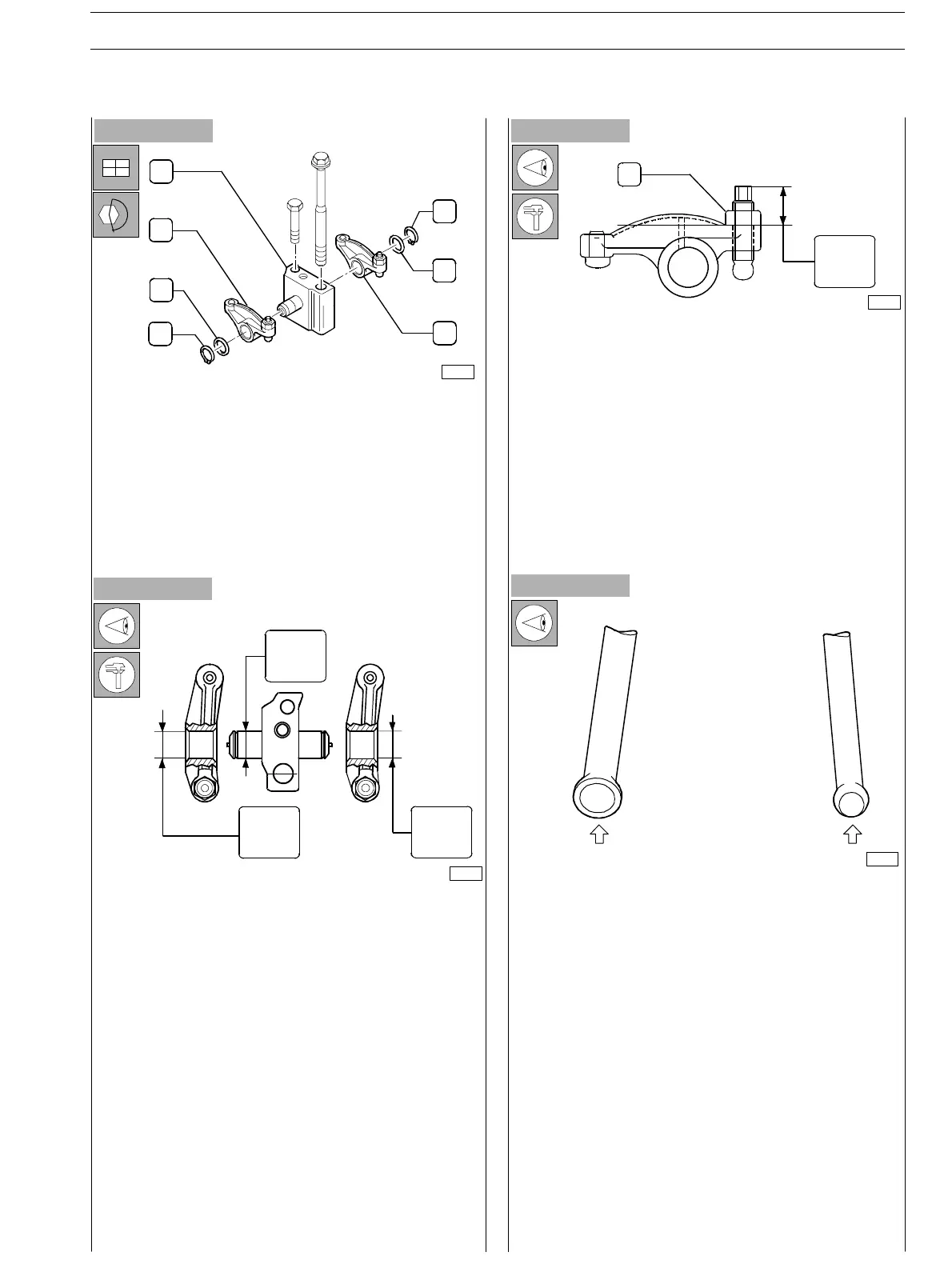
ROCKER ARM UNIT COMPONENTS:
1. Elasti c ring − 2. Spacer− 3. Rocker arms−
4. Support.
75704
18.975
18.963
19.000
19.026
19.000
19.026
1
19.00
16.00
75702
ROCKER ARM ADJUSTMENT SCREW
If unscrewed, check adjustment quota.
Tighten the screw−threaded nut (1) to the i 0.25 − 0.75 Nm
couple.
32655
Before executing assembly, check the Rocker Arm driving
rods: these shall not be deformed; the spherical ends in
contact with the Rocker Arm adjustment screw and with the
tappet (arrows) shall not present evidence of seizure or
wear: in case of detection proceed replacing them.
The rods driving the suction and exhau st valves are identical
and therefore interchangeable.
SECTION 3 − DUTY − INDUSTRIAL APPLICATION E NG I NE S
57
ED. FEBUARY 2003
zs