- 15 -
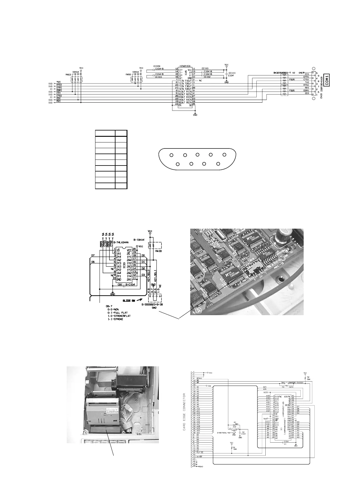
6-8. RS232C port COM1 circuit
The COM1 circuit is as follows:
The COM1 port pin location is as shown below:
Signal Pin
CD 1
RxD 2
TxD 3
DTR 4
GND 5
DSR 6
RTS 7
CTS 8
CI 9
1 2 3 4
5
6
7
8 9
6-9. Keyboard selection switch (Not mounted for CE-T300)
The main PCB has the keyboard selection switch to detect the keyboard type.
For the model CE-T300, the switch is not mounted. It is fixed as a stroke key type.
Keyboard selection switch
(Not mounted for CE-T300)
6-10. Flash Pack circuit (Memory Cassette RAC-9)
The Memory Cassette RAC-9 (2 M bytes) is possible to connect to the Flash Pack connector
CN1 of the Main PCB E479-1.
Flash Pack connector
[RAC-9 circuit diagram]
 Loading...


