- 16 -
6-11. To mount optional circuit
The following optional circuits are provided for model CE-T300.
1. Clerk key circuit
2. Multi-drawer circuit
3. Paper near end sensor circuit
1) Clerk key kit
NOTE: This circuit is mounted from factory for the destination Germany.
1-1. Prepare the following parts kit for clerk key circuit. The follwing parts kits are supplied from
sales division.
CLK-K19 Clerk key kit for 4 clerks
CLK-K20 Clerk key kit for 6 clerks
CLK-K21 Clerk key kit for 15 clerks
1-2. Check whether the parts of clerk kit are as follows:
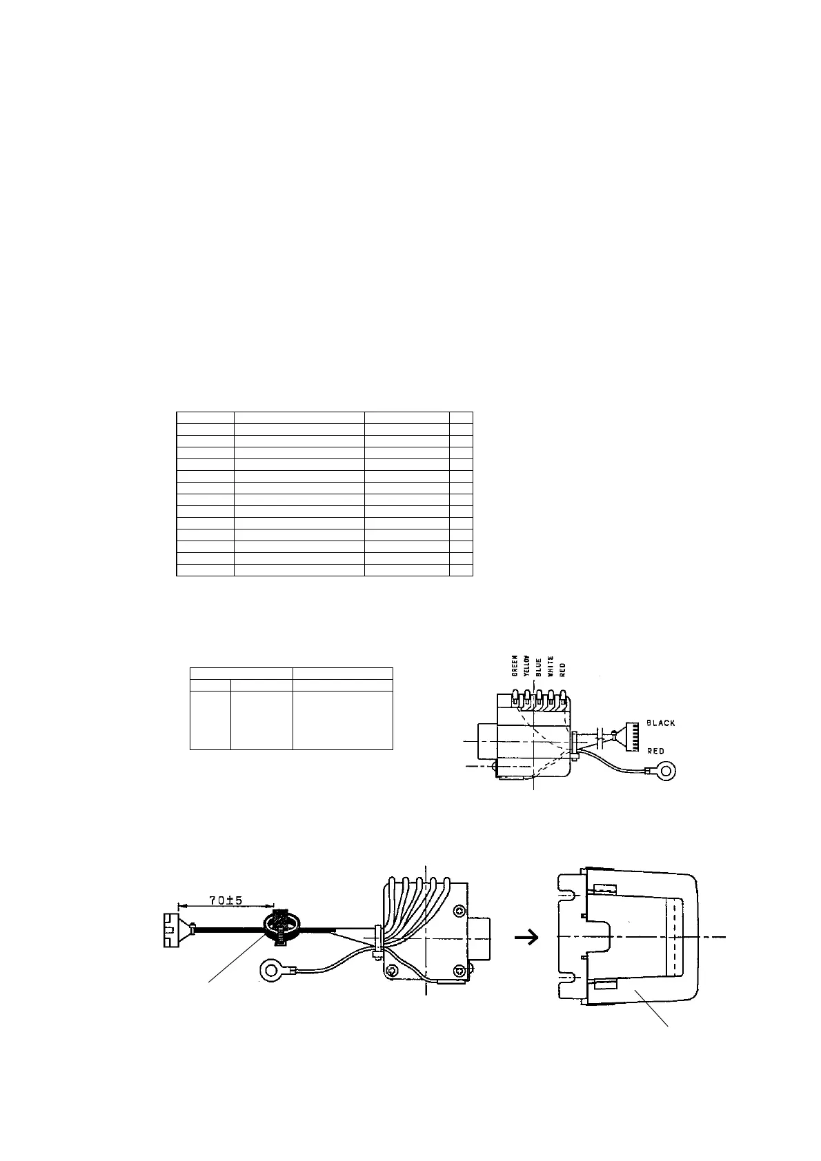
1-3. Connect the clerk key cable sub ass'y to the clerk key unit. Also, fix the FG wire by the fixing
pin and the screw.
1-4. Insert the clerk switch unit to the clerk key case.
Clerk cable sub ass'y Clerk key unit
Pin No. Wire color Printed mark on PCB
1 Red C
2 White 1
3 Blue 2
4 Yellow 4
5 Green 8
Turn 2 times
Ferrite core
Clerk key case
Code No. Parts Name Specification Q'ty
10003976 Clerk unit sub ass'y E340843A*1 1
34002576 Clerk key switch unit J-Y7541 1
62482225 Cleak key cable sub ass'y E440785B*1 1
38401238 FG wire fixing pin 23031-1 1
62158913 FG wire E32406-2 1
51115760 Screw 2.6 x 8 ZMC-3 1
55600368 Insulok tie T-18S 2
30304055 Ferrite core L5T18 x 6 x 10 1
10017367 Clerk key case E311204A-2 1
10003979 Clerk key set (4keys) 306JYB-135-02R 1
10011117 Mode key plate E340735A-23 1
10003980 Clerk key set (6keys) 306JYB-135-01R 1
10011785 Clerk key set (15keys) 306JYB-135-03R 1
 Loading...


