- 7 -
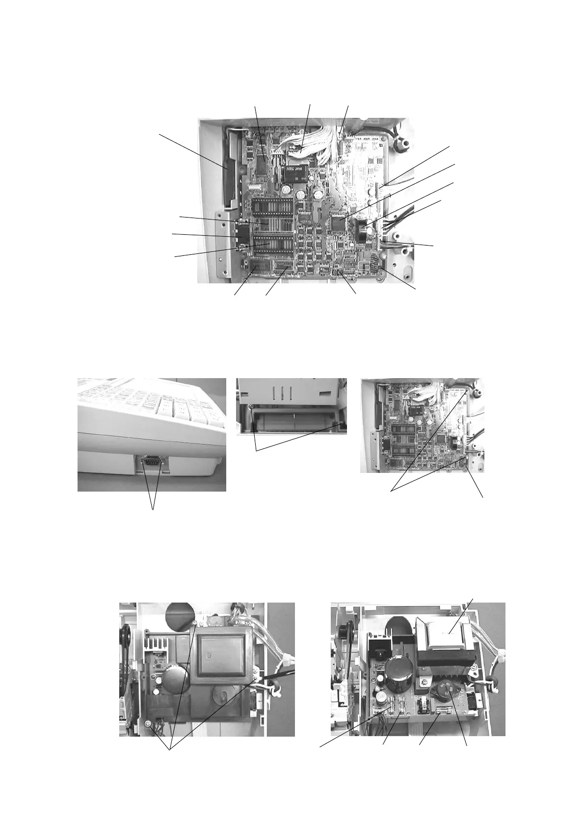
6. To remove the Main PCB, release the 2 screws of the Flash ROM cover and 2 locking
supporters of point A and the COM1 port outside 2 screws.
Remove 2 screws for COM 1 port.
5. The each parts of the Main PCB are located as shown in the picture.
Note: RAM2 is not used for CE-T300.
Battery
Flash ROM 1 (2 M bytes)
Main PCB
RAM 1 (128 Kbytes)
RAM 4
(Not used)
RAM 3
(Option)
COM 1 port
CPU
Buzzer
Printer cables
Display cable
Power supply connector
Reset Switch
Point A
Release the 2 locking supporters.
7. Power supply unit cover is removed by 3 screws. And, the 2 Fuses are located as shown in the
picture.
Main PCB
Remove the 3 screws.
Then, remove the power supply cover.
Power transformer
Voltage selector
Normally, Do not change
the Voltage position.
Fuse F1
250V 1A
Fuse F2
250V 2A
Fuse F3
250V 400mA
(Not used for CE-T300)
Clerk key connector
Keyboard select switch
(Not used for CE-T300)
RAM 2 (Not used)
Remove 2 screws for Flash ROM cover.
Then, remove the Flash ROM cover.
 Loading...


