— 28 —
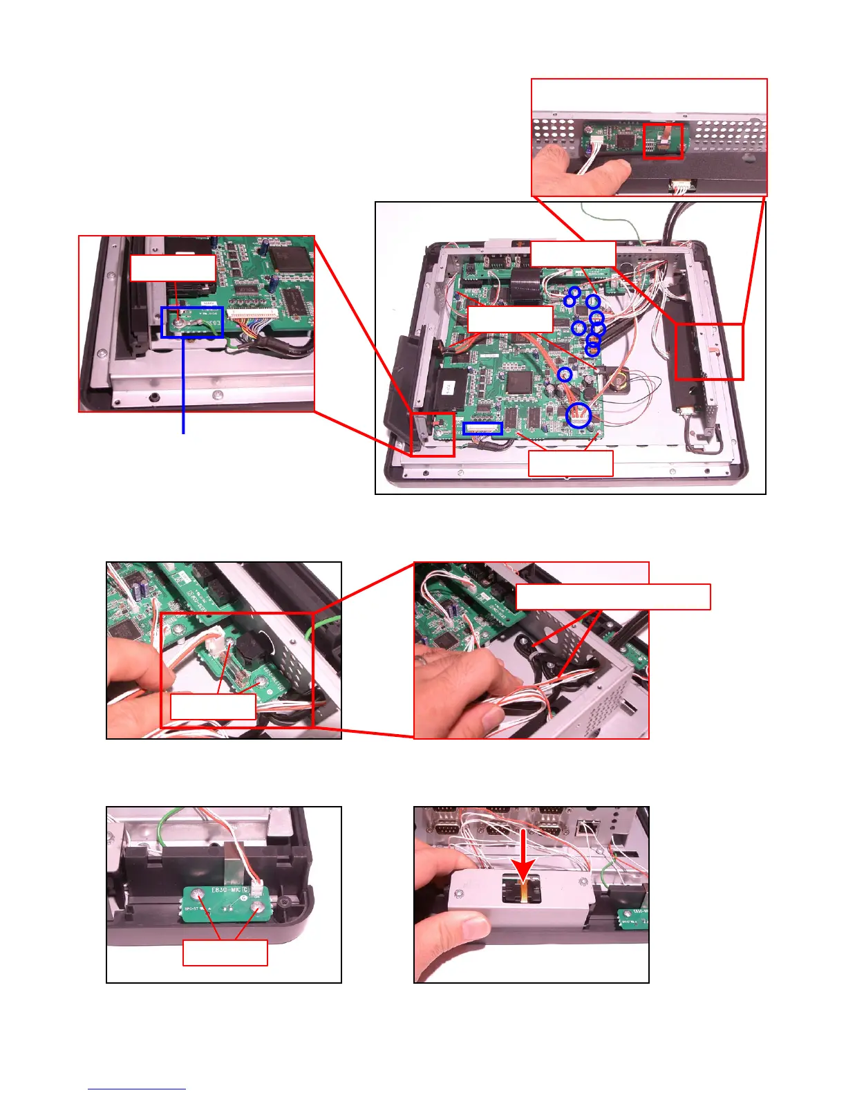
A-8. Plug 10 connectors and 1 FPC.
NOTE: Do not tangle the wires.
A-9. Secure it with seven screws.
A-10. Connect the Touch Panel PCB (E830-TP) to the FPC.
Screws (S9)
Screws (S9)
NOTE: Position it so that the earth terminal
is in the correct orientation.
Screws (S9)
A-12. Engage the Mic PCB (E830-MIC) and secure it with two screws.
A-13. Engage the MCR Unit.
Screws (S7)
Screws (S5)
A-11. Engage the Power Supply PCB (E830-INLET) and secure it with two screws.
NOTE: Two Drawer Cables are arranged under the PCB.
Screws (S9)
Drawer cables
 Loading...