– 3 –
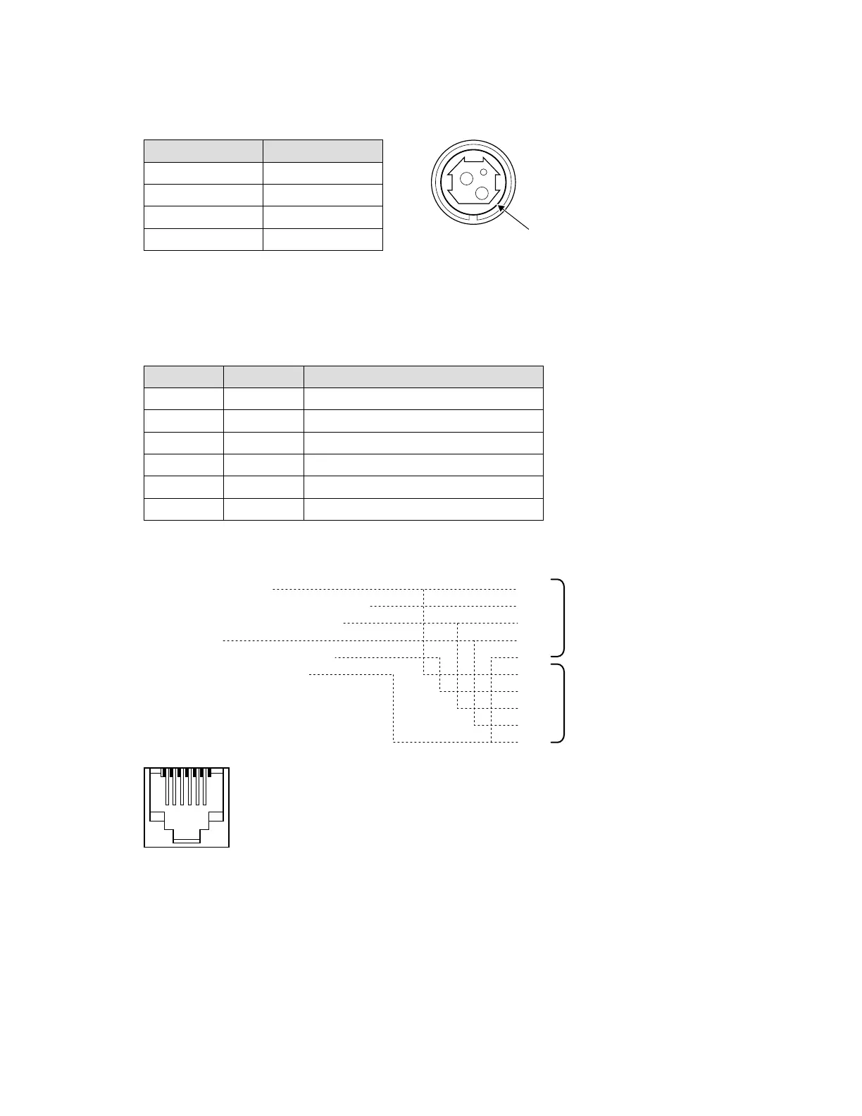
POWER SUPPLY CONNECTOR1-3-3.
The connector is connected the printer to an external power source.
Pin No. Signal
1 +24 V
2 GND
3 NC
Shell F.G
DRAWER KICK-OUT CONNECTOR1-3-4.
The pulse specied by ESC p or DLE DC4 is output to this connector. The HOST can conrm the
status of the input signal by using the DLE EOT, GS a, or GS r commands.
Pin No. I/O Description
1 - Frame ground
2 Output Drawer kick-out drive signal 1
3 Input Drawer open/close signal
4 Output +24 V
5 Output Drawer kick-out signal 2 *
6 - Signal ground
Two drawers can be used with a Y-cable that meets the following specications.*
Pin 1: Frame ground
Pin 2: Drawer kick-out drive signal 1
Pin 3: Drawer open/close signal
Pin 4: +24 V
Pin 5: Drawer kick-out signal 2
Pin 6: Signal ground Pin 6
Pin1
Pin2
Pin3
Pin4
Pin6
Pin1
Pin2
Pin3
Pin4
Pin6
Connector of Drawer No.1
Connector of Drawer No.2
CONNECTOR MODEL:
Printer side: MOLEX52065-6615 or equivalent
Used side: 6-position 6-contact (RJ12 telephone jack)