IV - SELECTION OF STAPLING POSITION
The CS 910 is designed to enable wedging of mouldings at 1 or 2
points, with one or several wedges stacked at each of these two
positions.
The choice must be made according to the width and the height of
the moulding.
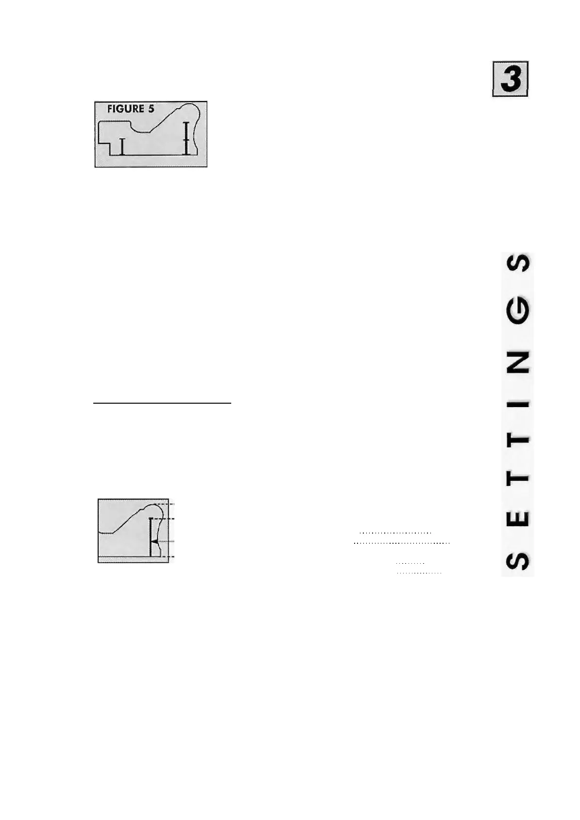
NOTE : IN ALL CASES, WEDGES MUST BE INSERTED AS CLOSE AS POSSIBLE
TO THE HIGHEST CROWN OR CROWNS OF THE MOULDING (FIGURE 5)
Release operating levers X and W (FIGURE 1)
Place one moulding against fence M and slide it as far as stop N (FIGURE 2)
a) First position : inside of frame :
Slide bracket E towards fences M and N until the selected stapling position is reached, and draw
operating lever W towards you to the position and lock it.
b) Second position : on the outside of the frame.
Slide bracket E towards fences M and N until the stapling position is reached, and push operating
lever X to the position, and lock it.
TIP : Use the measuring stickers next to both stops W & X to determine the
best selections of wedging positions for your mouldings.
V - SELECTION OF WEDGES
The size of the wedges (5, 7, 10, 12 or 15 mm - 3/16", 1/4", 3/8", 1/7", 5/8") must be
selected on the basis of the height of the moulding . As a general rule a minimum allowance of
2 mm (2/25") is made above the wedge.
E.g.: Moulding thickness 12 mm (1/2") : 10 mm (3/8") wedge (see below)
WEDGES' SIZES CARTRIDGE COLORS
2 mm (2/25") minimum
Wedge 12 mm (1/2°)
5 mm (3/16") ORANGE
7 mm (1/4") PINK
10 mm (3/8"
12 mm (1/2"
15 mm (5/8"
BRIGHT BLUE
DARK BLUE
WHITE
*Two types of wedges : for normal
and hardwood (see bellow NOTE 2)
NOTE 1 : Wedges of the same size may be stacked (FIGURE 6), in order to avoid the need
for changing the cartridge, if you are joining frames of different thicknesses.
NOTE 2 : There are also wedges made especially for hard woods (BD).where standard
wedges would not be adequate, i.e. they would bend, break or fail to penetrate entirely.
910SRJR/02.94
-5-
 Loading...