28
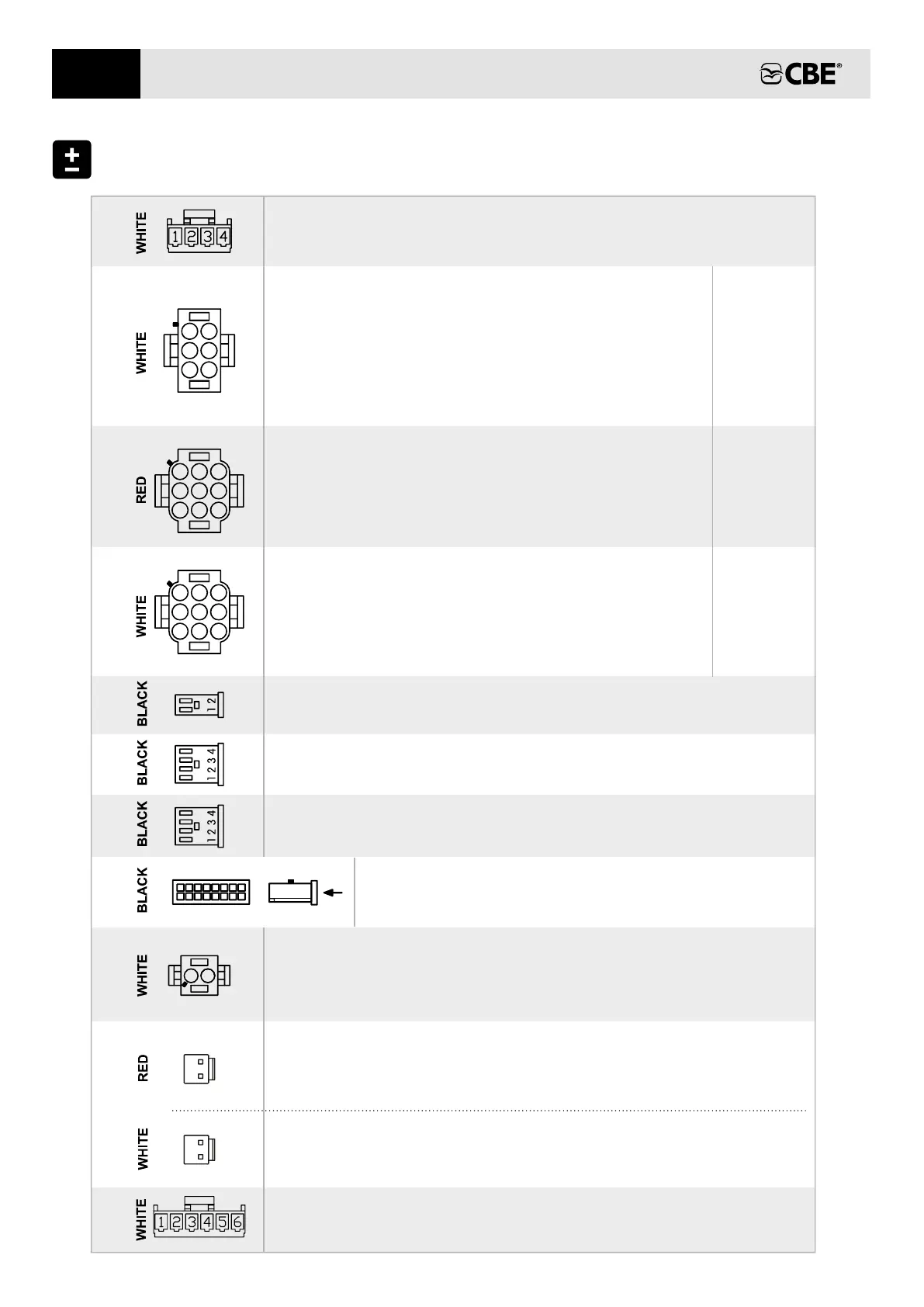
SIGNALS (OPTION A )“ ”
2) + input signal “S” net coming from the CBE battery charger.
1) + input signal contact key engine starting.
SIGNALS (OPTION “B”)
2 ) + input signal contact key engine starting.
1) - input “D+” negative signal (-)
1) + input signal “S” net coming from the CBE battery charger.
2 /)
1
2
1
2
26B)
27)
NOT CONNECTED
23)
To connect to the waste water tank probe
WASTE WATER TANK(RE-EL)
USERS
2) + exit water pump; it depends on the pump button.
7-8-9) + exit lights group "B”; it depends on button.12V
3) Not connected.
1) + exit heating/boiler; it depends on the o
n/off
button
main
.
4 ; -5-6) + exit lights group "A" it depends on button.12V
FUSIBILE
12
11
13
14
7
21)
1
4 7
2
5 8
3
6
9
USERS
19)
1
4
2
5
3
6
1) + exit RH; it depends on the o
n/off buttonmain .
2) + exit gas pump supply depends on the ; it o
n/off
button
main
.
6) + exit RH; it depends on the o
n/off buttonmain .
4-5) + exit TV sockets it depends on the ; o
n/off buttonmain .
3) + exit AUX (awning light), awning lightit depends on the
button.
FUSE
3
2
1
4
5
24)
FRESH (POT) WATER TANK
To connect to the water tank probe.fresh
22)
NOT CONNECTED
USERS
1) + exit AUX (direct “B2”)
5-6-8-9) exit gas users (fridge, k , ecc ...) (direct “B2”)itchen
2-3) + exit 3 way function fridge / AES
4) + exit electric step (direct “B2”)
FUSE
8
6
9
10
20)
1
4 7
2
5 8
3
6
9
NOT CONNECT
18)
CONNECTIONS
1
9
8
16
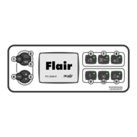
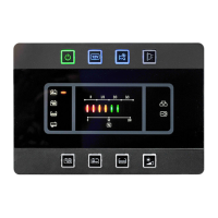
CONTROL PANEL
To connect to the 16 poles connector of the control panel.
25)
1 2
26A)
EN