Technical manual Tild v1.0QC
for 12VAC and /24 for 24VDC). If the light(s) is supplied in 12VAC, put a 12VAC
power supplied and verify the Tild P/N. If the light is supplied in 24VDC put a
24VDC power supply and verify the Tild P/N.
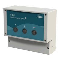
Pass all the cable of the devices into the dedicated cable gland and connect them to the dedicated terminal
block.
Example of a full wired diagram:
When all the devices are connected, put in place the lower cover and tighten the screws at 1.2 Nm.
Tight the cable gland.
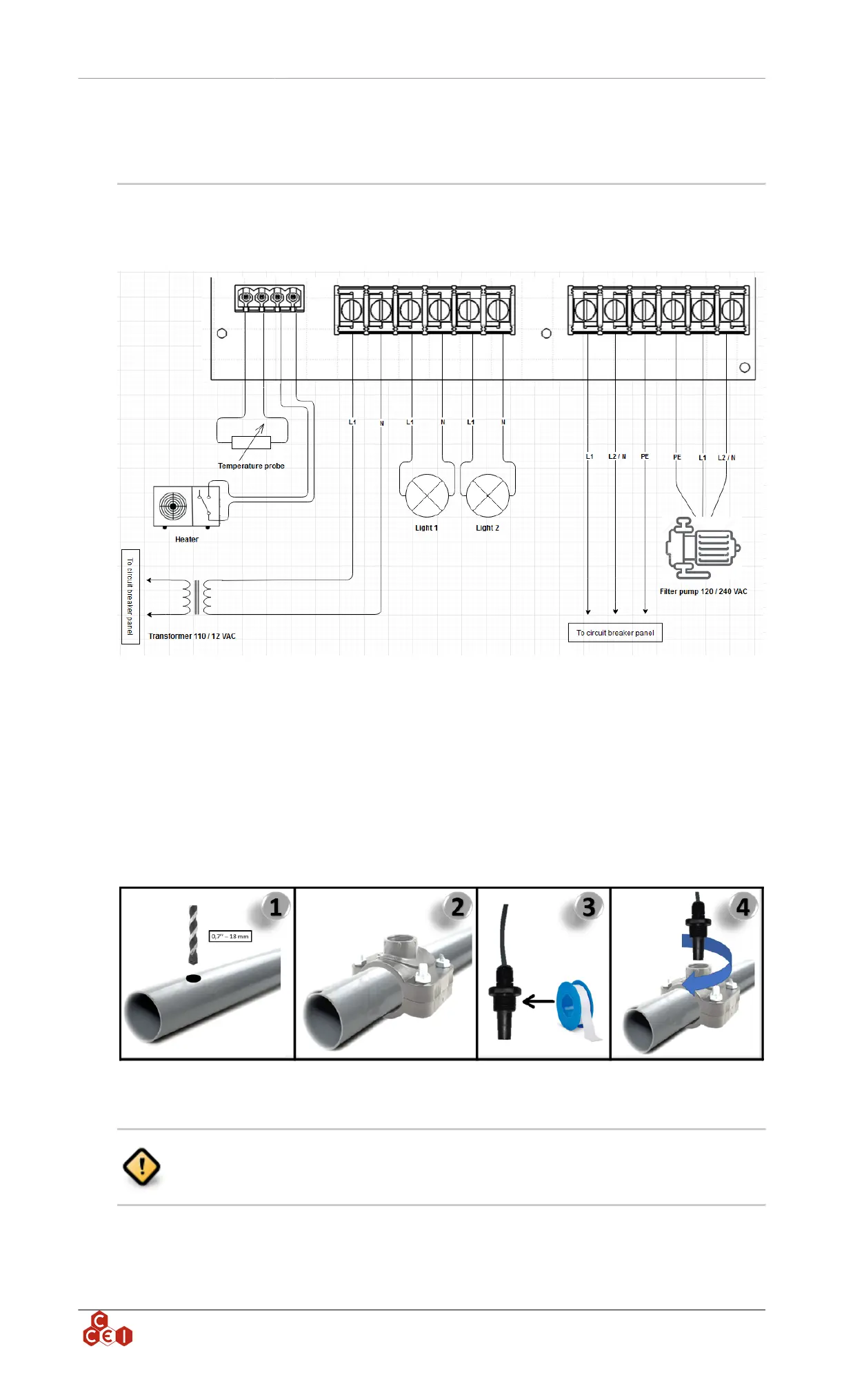
5.1. Temperature probe mounting
1. On your piping, drill a 0.7 " (18 mm) diameter hole on the high point of the pipe
2. Fit the collar supplied with the product (select the collar with the appropriate diameter)
3. On the temperature probe, put Teflon on the thread of the probe
4. Screw the probe into the upper hole of the collar
5.2. Heater wiring
Before wiring the heater, read carefully the section dedicated to remote controlling
into the heater manual. Process can be different from one heater to another.
Most heaters can use a remote connection and will be compatible with the Tild . When connecting a
heater to the Tild , the water temperature sensor must be installed into the plumbing system between
the filter pump and filter.
ccei.ca
5