OPERATING INSTRUCTIONS
Ofix VP v1.0EN
4.2. Connection to electricity
Installation of this project involves a hazard of electric shocks. We strongly recommend you
contract a professional installer. Incorrect installation puts you in danger and may irreversibly
damage the product and the equipment connected to it.
For safety reasons, and in accordance with the French NF C15-100 standard, the Ofix VP power
supply block must be installed
• either at over 3.50 m from the pool edge. This distance takes into account the distance around
obstacles. If the Ofix VP power supply block is installed behind a wall, the distance will
include the length of the path taken to move around the wall to reach the box.
• or in an in-ground space in the immediate vicinity of the swimming pool. In this case the
space must be accessible via a hatch which requires a tool to open it.
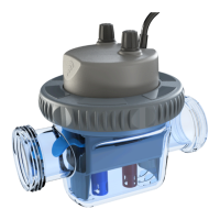
The Ofix VP connected analyser:
• must not be directly installed outdoors, it must be sheltered from rain, cleaning or watering spray, and UVs (sunlight).
• is spray resistant but must not be installed in a floodable area.
The box is shipped with a power supply cable that can be connected to the mains in the technical room using a standard plug
and socket (230V / 50 Hz). This socket must be protected by a 30mA ground fault circuit breaker in compliance with
the NF C15-100 standard.
The appliance is fitted with a flow switch and must not be installed on a power supply line that
is coupled to the filtering. This could cause the appliance to malfunction
5. Start up / configuration
Ofix VP must be configured using the Vigipool smartphone app available for iOS and Android.
At the very first start-up, the built-in RGB LED flashes white. By pressing the button, you confirm the ''Master'' role of your
analyser and you will be able to connect other appliances in the future (dosing pumps in particular).
The button is also used to:
• Calibrate the pH and ORP sensors
• Restart/reset the appliance (long press for about a dozen seconds)
5.1. Choice of the Vigipool ''central unit'' appliance
Please refer to the attached ''Vigipool World'' page for more information
At the end of the initialisation phase, the Ofix VP flashes white. This corresponds to the choice of the appliance that will perform
the Vigipool ''central unit'' function (see attached specific ''Vigipool World'' page):
• If the installation only has this appliance, press the selection button (A). The appliance is then configured as a Vigipool
''central unit'' and other appliances can be added to the installation later.
• If the installation has several Vigipool World compatible appliances
– If an appliance is already configured as a Vigipool ''central unit'', press the button on the Vigipool ''central unit'' if it has
been powered on for more than one minute. (If it has been powered on for less than a minute, there is no need to press its
button). Your Ofix VP then connects to the Vigipool ''central unit'': It stops flashing white and switches to normal operation.
– If no other appliance is already configured as a Vigipool ''central unit'', turn on all the appliances and press the button on
the appliance you want to use as a Vigipool ''central unit''. The other products will then connect to the appliance you have
validated as the Vigipool ''central unit'', they stop flashing white and switch to normal operation mode.
6
 Loading...