EN EN
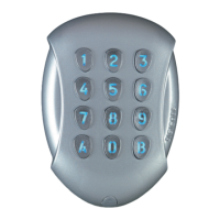
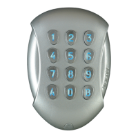
DGA
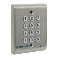
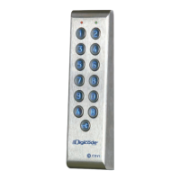
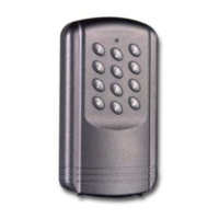
Keypad DGA
4 cdvigroup.com
P1
H
V
V
V
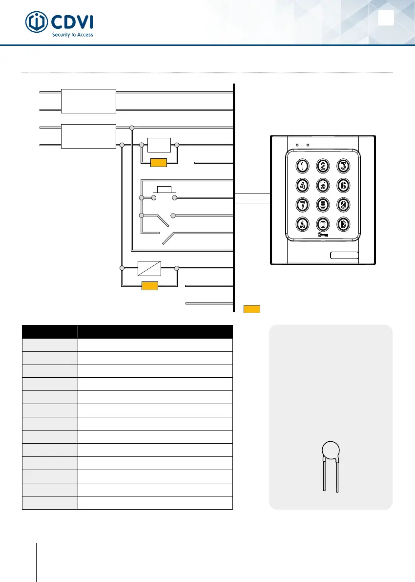
5] WIRING DIAGRAM
This device comes with a
varistor. The varistor must
be connected on the strike
terminal (electromagnet…)
operated by the device. If
this product operates more
than one strike, each lock
should have a varistor. The
varistor controls the overload
produced by the strike coil –
back emf.
Wires Description
Black Input voltage 12V or 24V AC or DC
Red Input voltage 12V or 24V AC or DC
Brown Relay 1 N/C contact
Pink Relais 1 common
Orange Relay 1 N/O contact
Yellow Common
Dark Green Relay 1 request-to-exit input
Light Green H Timer input
Blue Usercodemodication
Dark Blue Relay 2 N/C contact
Purple Relais 2 common
Gray Relay 2 N/O contact
White Reset
Varistor
INPUT VOLTAGE
12Vac to 24Vac
12Vdc to 48Vdc
INPUT VOLTAGE
Locking devices
230 V
ELECTROMAGNET
Black
Red
Pink [C1]
Brown [NC]
Orange [NO]
Yellow
Dark green
Light green
Blue
Purple [C2]
Gray [NO]
Dark blue [NC]
White
STRIKE
RESET
230 V