CEBORA S.p.A. 20
5.3
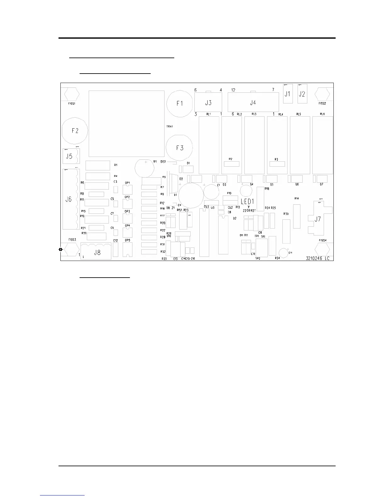
- Control board (4) code 5.602.146.
5.3.1 - Topographical drawing.
5.3.2 - Connector table.
Connector Terminals Function
- J1 – J2 230 Vac output for fan (34) power supply.
J3 1 – 2 wired bridge for fan (34), solenoid valves and contactors power supply.
J3 4 – 5 NU.
J3 3 – 6 230 Vac input for control board (4), fan (34), solenoid valves and contactors power
supply.
J4 1 – 7 contactor TLM (32) command output.
J4 2 – 8 contactor TLP (32) command output.
J4 3 – 9 NU.
J4 4 – 10 solenoid valve ELT (6) command output.
J4 5 – 11 NU.
J4 6 – 12 solenoid valve EL1 (7) command output.
J5 - NU.
J6 1 – 2 start signal input from torch button.
J6 3 – 4 – 5 pressure signal input from pressure switch (8).
J6 6 – 7 temperature signal input from thermostats on transformer (38).
J7 1(+) – 4(-) power source output voltage signal input.
J8 1 – 2 lamp L (39) command output (pressure insufficient).
J8 3 – 4 lamp G (39) command output (overtemperature and code alarms).
3.302.170 06/07/04