CEBORA S.p.A. 8
3.3
- Troubleshooting.
WARNINGS
ANY INTERNAL INSPECTIONS OR REPAIRS MUST BE CARRIED OUT BY QUALIFIED
PERSONNEL.
BEFORE REMOVING THE PROTECTIVE GUARDS AND ACCESSING INTERNAL
PARTS, DISCONNECT THE POWER SOURCE FROM THE MAINS.
NOTE
Items in boldface describe problems that may occur on the machine (symptoms).
Operations preceded by this symbol refer to situations the operator must determine (causes).
♦ Operations preceded by this symbol refer to actions that the operator must perform in order to
solve the problems (
solutions).
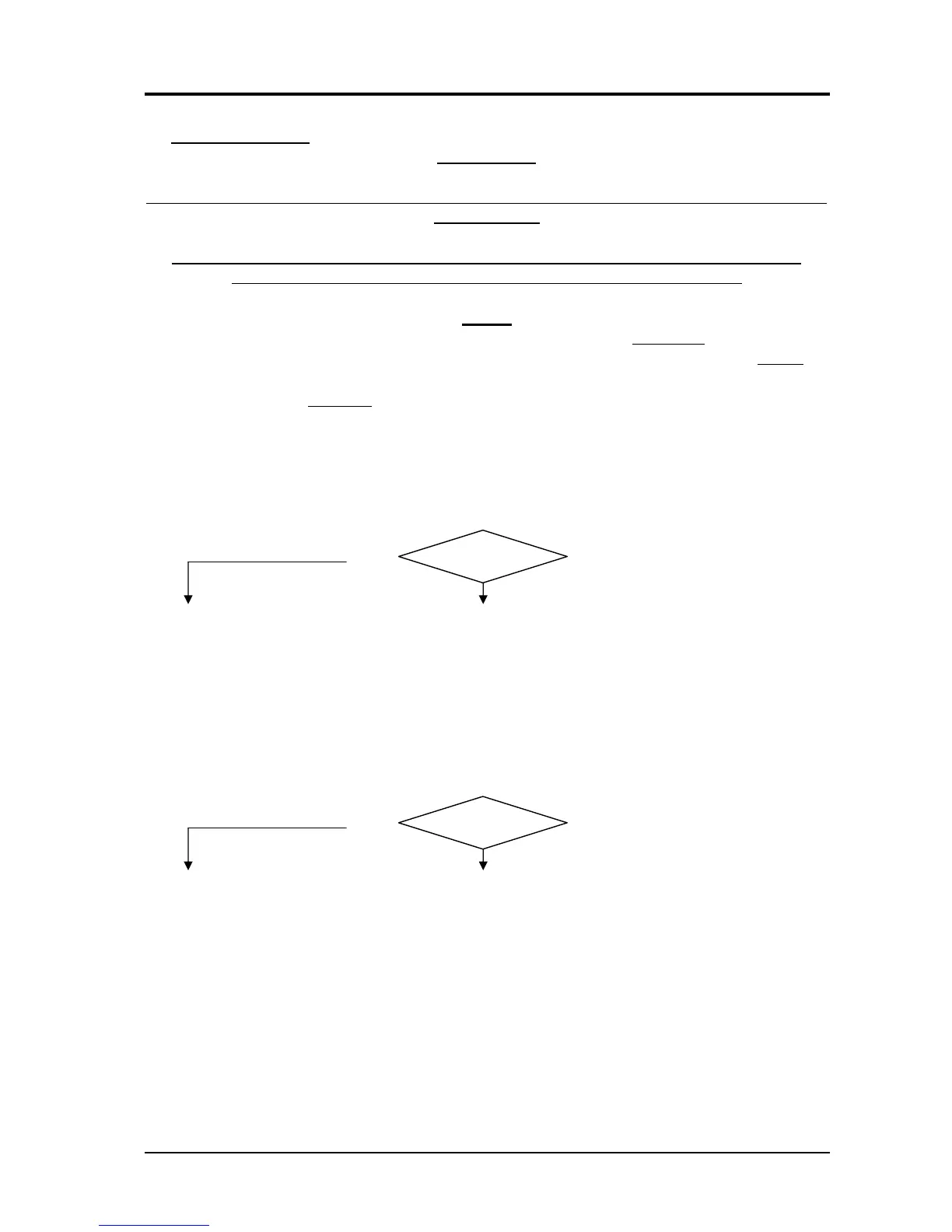
3.3.1 - The power source does not start, lamp (22) off, fan (34) stopped.
MAINS SUITABILITY TEST.
Correct?
Missing voltage at the power source input due to tripped mains protections.
NO
YES
♦ Eliminate any short-circuits or insulation leakage toward earth of the connections
between power cable, switch (40), transformer (38) and control board (4).
♦ Check the insulation towards earth of the transformer (38) and fan (34). If leaking
or short-circuited towards earth, replace.
♦ Mains not suited to power the power source (ex.: insufficient installed power).
MAINS CONNECTION TEST.
Correct?
Terminals U, V and W of switch (40) = 3 x 400 Vac approximately (or 3 x 230 Vac
approximately according to mains voltage) with switch (40) closed.
YES
NO
♦ Check power cable and plug and replace if necessary.
♦ Check switch (40) and replace if defective.
♦ Check the mains voltage conditions, and especially that none of the three power
supply phases is missing.
CONTROL BOARD (4) POWER SUPPLY TEST.
Control board (4), connector J3, terminals 3 and 6 = 230 Vac approximately, both with mains
at 230 and at 400 Vac.
Control board (4), connector J6, terminals 1 and 2 = 24 Vac approximately.
Control board (4), connector J7, terminals 4(-) and D1 diode cathode (+) = +15 Vdc
approximately; connector J7, terminals 4(-) and D1 diode anode (+) = +5 Vdc approximately.
All with switch (40) closed and both with mains at 230 and at 400 Vac.
3.302.170 06/07/04