16
• CEDIMA® • Technical Documentation • All rights reserved according to ISO 16016 • Changes serving technical progress reserved •
Set-up and operation
Joint cutter CF•22 E
4.2 Mounting the diamond saw blade
4.2.1 General information on mounting
The drive unit of motor and cutting shaft RPM are designed
to provide optimal conditions for cutting with CEDIMA®
diamond saw blades!
Choose the right kind of diamond saw blade for the mate-
rial to be cut!
Observe the diameter of the shaft hole (spindle diameter)
and of the cutting shaft.
Please refer also to chapter “technical data and accessories”.
If the shaft hole diameter of your saw blade is larger, use an
appropriate reducing ring!
The maximum permissible saw blade diameter is 700 mm!
Detailed information about the proper saw blade types and
reducing rings are to be obtained from CEDIMA®!
CEDIMA® can not accept any warranty in case of incorrect
use of diamond saw blades!
Complaints concerning diamond saw blades supplied by
CEDIMA® can only be accepted if the diamond segments
show a minimum remaining segment height of 20 %!
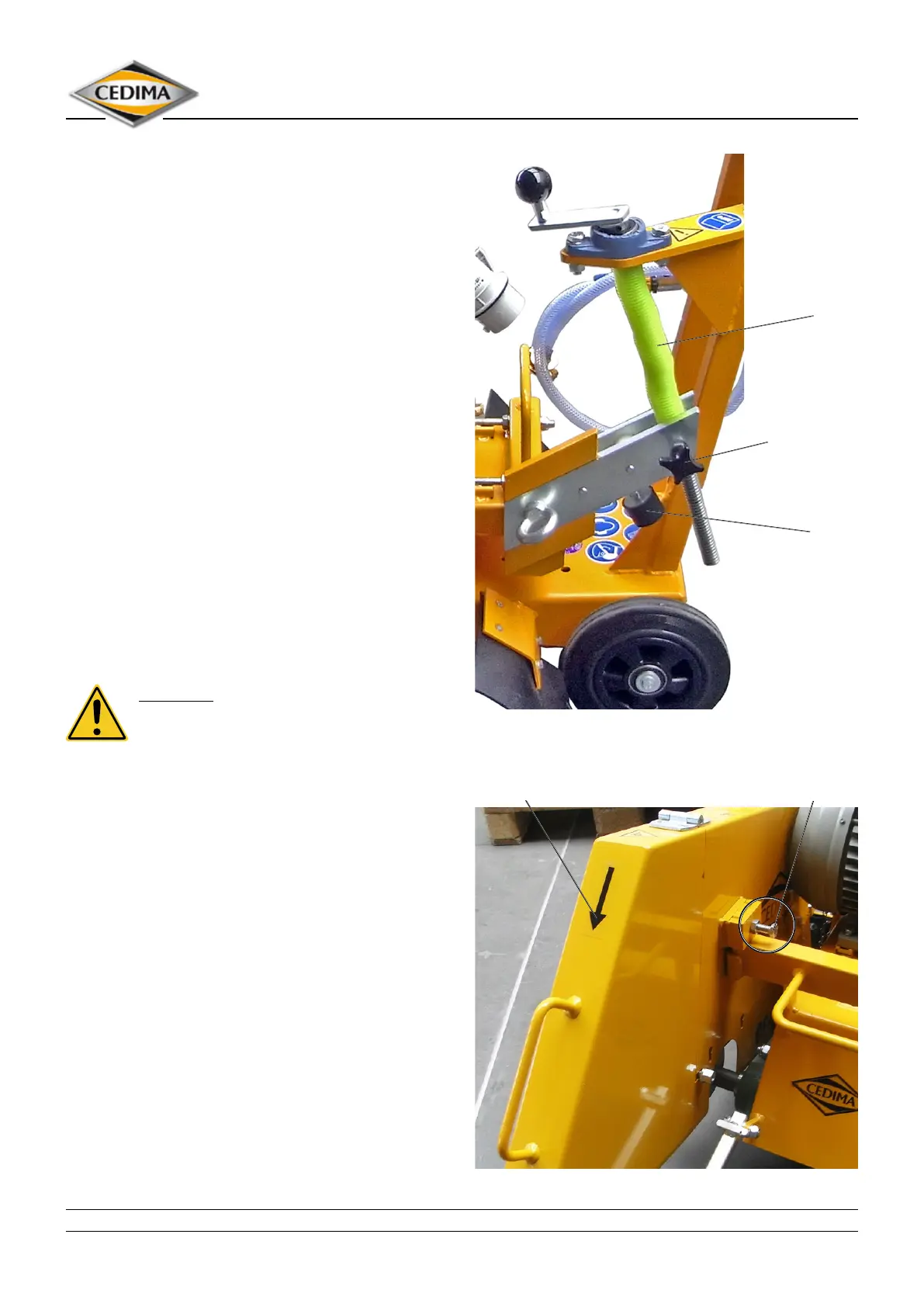
4.2.2 Lifting the cutting shaft
DANGER!
Make sure that the joint cutter can not be
started unintentionally by isolating the motor
from the power supply!
Loosen the star-knob screw which locks the lifting spindle.
Turn the spindle by means of the hand crank until the
blade arm reaches its maximum height. At the same time
the machine is braked by the stopper.
Figure 4.4
Spindle
Star knob screw
for locking
the spindle
Stopper
Loosen the clamping screw on the blade guard and lift it
upwards from the machine.
Figure 4.5
Directional arrow Clamping screw