15
• CEDIMA® • Technical Documentation • All rights reserved according to ISO 16016 • Changes serving technical progress reserved •
Set-up and operation
Joint cutter CF•22 E
4.0 Set-up and operation
4.0.1 To be checked on delivery
First check the completeness and intactness of your
CEDIMA® joint cutter CF•22 E. You will nd the scope of the
delivery in the chapter “Technical data and accessories”.
The joint cutter can be put into operation with no special
eort or installation procedure. However, when setting up
and operating the machine it is important to observe the
notes shown below, as well as the general safety regu-
lations and safety instructions for the operation of the
engine.
4.1 Preparing the joint cutter
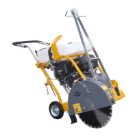
4.1.1 Assembling/dismantling
the joint cutter
Assembling:
– Grease all connecting elements before each assembly.
– Place rocker with motor and cutting shaft down into the
bearin on the trolley.
– Insert the central bolt and secure by means of the spring
pin.
– Fix the connecting plate for the hight adjustment onto
the rocker using the ring bolt. The connecting plate must
be located in the upper section of the threaded spindle.
– Attach the blade guard.
Dismantling:
– Proceed in reverse order to Assembling.
Figure 4.1
Bearing of the trolley Blade guard
Spring cotter pin
Rocker with motor
and cutting shaft
Arm extension of the
hight adjustment
Central bolt
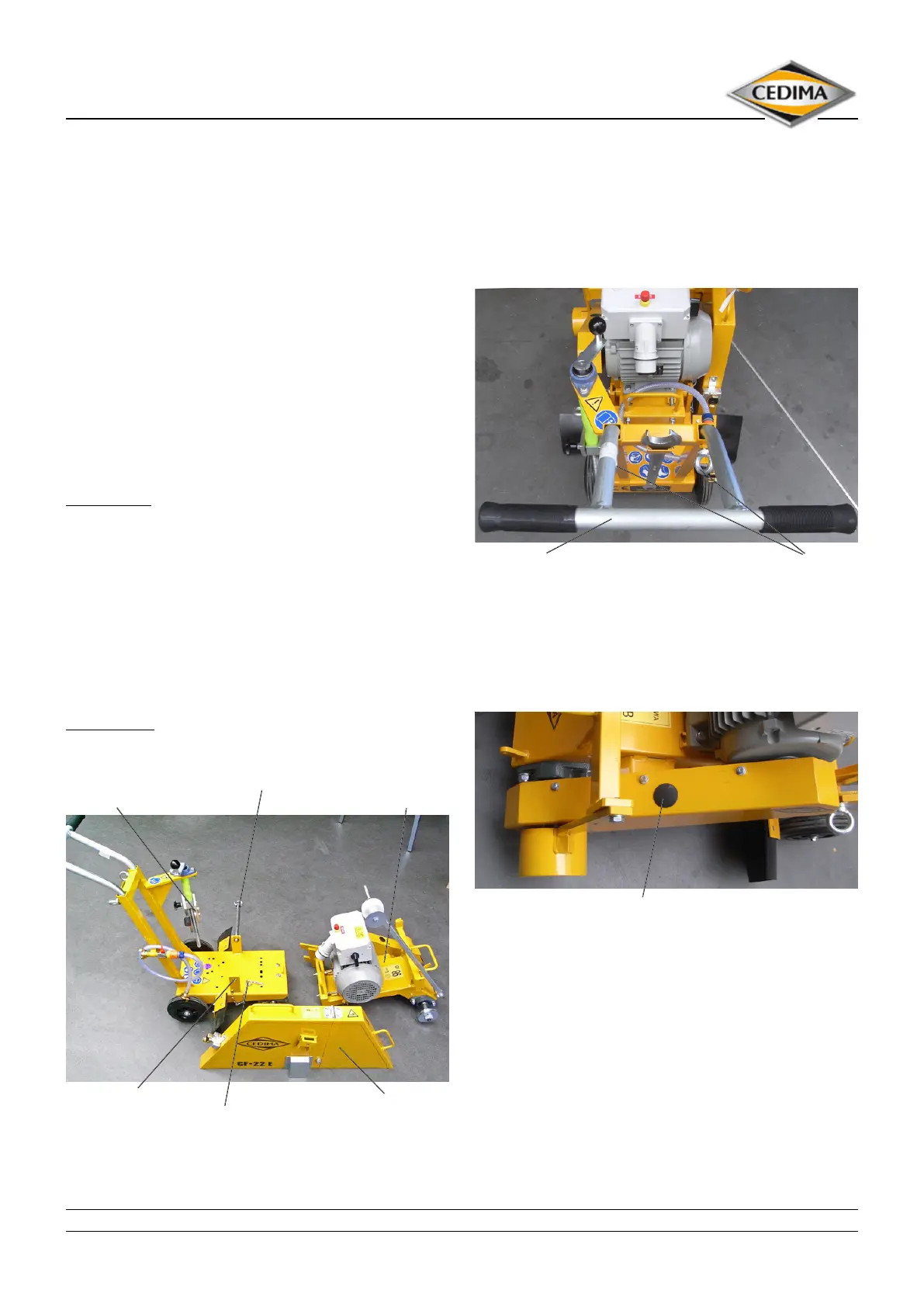
4.1.2 Adjusting the push handle
Release the ring bolts and pull out the push handle ap-
propriate to your height until you can move the joint cutter
comfortably.
Lock the push handle in the desired position by means of
the ring bolts.
Push handle Eye bolts
Figure 4.2
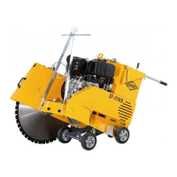
4.1.3 Checking the V-belts tension
Check the tension of the V-belts daily!
V-belt cover with plug Figure 4.3
The tension of the V-belts is checked as follows:
Disconnect the joint cutter from the mains by pulling the
plug!
Remove the plug of the V-belt cover at a motor standstill.
The plug is located on top of the belt cover.
Check the now accessible V-belts through the control
opening by pressing the belts with your ngers. It should
only be possible to press the belts about 10 mm down-
wards. If they can be pressed further they need to retight-
en.
The tensioning and changing of the V-belts is described in
chapter “care and maintenance”.