19
• CEDIMA® • Technical Documentation • All rights reserved according to ISO 16016 • Changes serving technical progress reserved •
Set-up and operation
Joint cutter CF•22 E
ATTENTION!
Connect the electrical connections properly!
Working on electrical mains and electric motors
may only be carried out by electricians or by persons under the
supervision of electrical specialists according to the electro-
technical rules. Observe the specic rules and regulations of
the country in question!
For use on a construction site, the connections must be on a
power supply according to IEC (EN) 61439 und 60364-7-704 a
building site power supply!
Pay attention to the relevant safety information for operating
electrical systems, e.g. DGUV 3 of BGHW, the respective VDE
specications and the relevant measuring (standard) e.g. EN
60 204-part 1!
ATTENTION!
Observe specications for connecting the mains power
supply cable!
The mains power supply cable, the cable drum must be
according to the connected values and be released for the
outer area!
Never connect with the mains power supply cable wound onto
the cable drum since power losses can occur on the joint cutter
due to the heat resistance!
From a cable length of 50 m losses in performance arise on the
joint cutter!
From a cable length of 100 m losses in performance increase
strongly!
The losses in performance can be almost completely compen-
sated for by using appropriate cable cross sections:
Pay attention to the cross-section equivalent to the lengths of
the electric connections:
up to 20 m –> 5 x 4 mm²
up to 50 m –> 5 x 6 mm²
up to 100 m –> 5 x 10 mm²
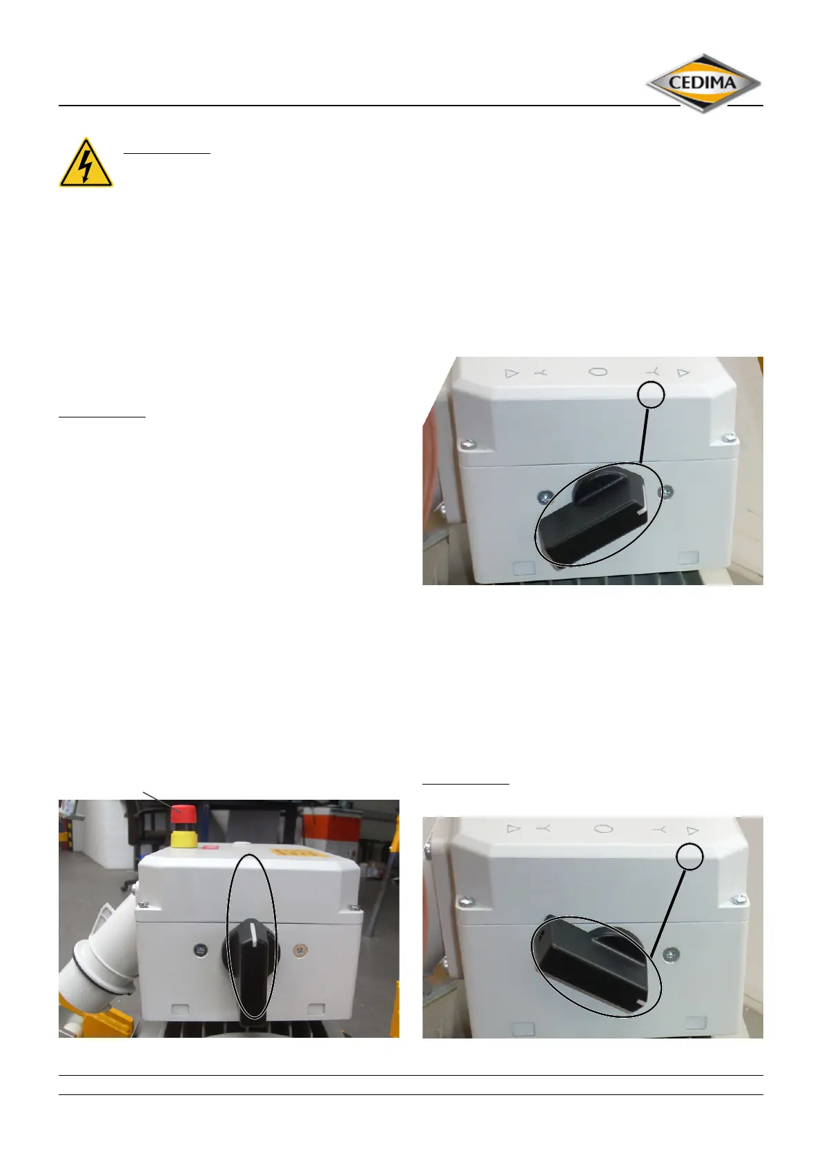
∆ Y 0 Y ∆
CF-22 E switched o Figure 4.12b
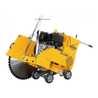
Emergency-stop button
The saw blade will start rotating on operating the motor
switch. Make sure that no danger might occur from the
rotating saw blade!
Turn the star-delta reversing switch right to Y position
until the saw blade begins to turn, then turn the star-delta
reversing switch left, back to 0.
The saw blade is slowly running down. Observe the rota-
tional sense of saw blade. The rotational sense of the saw
blade must correspond to the direction indicated by the
arrow on the blade guard (the rotational sense of the ven-
tilator wing must correspond to the arrow on the ventilator
cover).
∆ Y 0 Y ∆
Star-delta reversing switch switched in Y-position Figure 4.12a
When the rotational senses match, turn the star-delta
reversing switch again right to position Y. Wait until the
motor has reached the nal number of revolutions, then
turn the star-delta reversing switch further right to Δ.
If the direction of rotation of the saw blade is wrong, switch
the star-delta reversing switch to the left and, when the
nal speed is reached, swith it further to the left into the
Δ
position.
ATTENTION!
Only operate the machine in the Δ position!
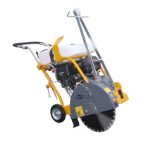
∆ Y 0 Y ∆
Star-delta reversing switch switched in ∆-Position Figure 4.12c