6
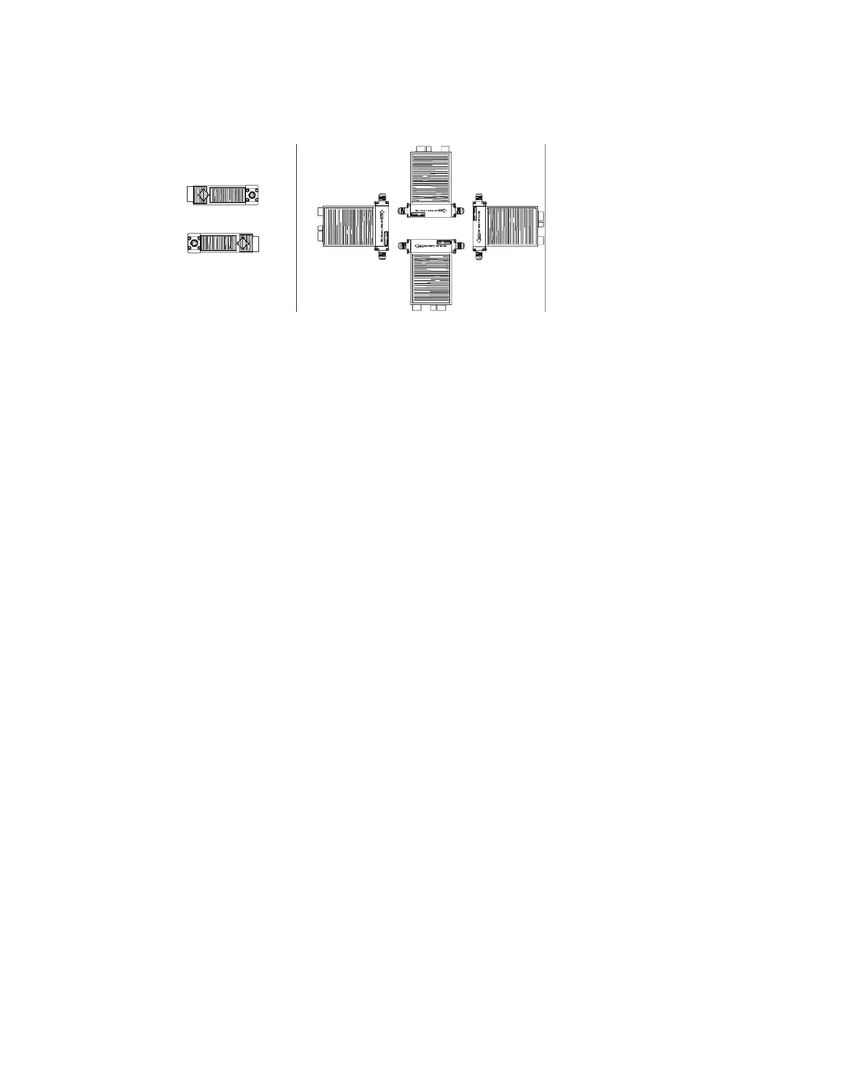
Mounting Attitude
Figure 1. Mounting Attitudes. Two Configurations: HOS and HOV
In order to provide optimum performance, Celerity calibrates all Mass Flow Controllers
and Mass Flow Meters to the position specified at the time of the order.
7.4 Mounting the Controller
Use two #8-32 screws to mount the controller. This will ensure the flow controller's
resistance to vibration from external sources.
7.5 Connecting to gas supply line
Once the unit is correctly mounted, connect the inlet and outlet fittings of the controller to the
gas supply line. Depending on the type of fittings used, connect and tighten per fitting
manufacturers specifications.
NOTE: You MUST use two wrenches to tighten each fitting of the unit, one for the nut and the
other to keep the fitting from receiving any rotational stress. If you do not do this you
could cause a leak, due to stress applied to the MFC’s internal seals.
8. ELECTRICAL CONNECTIONS
8.1
Voltage and Pinouts
- Check that the pin connections of the mating cable have the same pinout
(See Appendice 16.1).
- Most analog and digital MFCs use ±15 VDC power.
- DeviceNet MFCs use +11-25 VDC power
.
- A Flow meter has the same pinout as a controller, except that the following pinouts do not
apply on a meter:
- Setpoint, V
alve T
est Point, V
alve Off
- Auto-Zero Disable, Auto-Zero Alarm.
NOTE: Do not make any connections to any unlabeled connector pins.
HOS
Horizontal-On-Side
HOV
Horizontal-Or-Vertical
©2005 Celerity
, Inc.
#199-001-0006 REV
.F 4/05
Artisan Technology Group - Quality Instrumentation ... Guaranteed | (888) 88-SOURCE | www.artisantg.com