14
ENG
2.8.2 Instructions special stainless
steel venting system for use
with Category III appliances
Z-FLEX recommends that an experienced pro-
fessional who works with venting systems on
a regular basis perform the installation. These
instructions are intended as a guide to assist
a professional installer.
When the Z-VENT system is installed, the
following should be observed:
1. A venting system that exits the structure
through a sidewall or the like, shall termi-
nate not less than 12 inches (254 mm)
above the ground (see figure 6/a, page
22).
2. The termination of a system shall be loca-
ted above the snow line in geographical
areas where snow accumulates. The ter-
mination area should be kept clear of snow
and ice at all times.
3. The vent shall not terminate less than 7 ft.
(2.13 m) above a paved sidewalk or drive-
way.
4. The termination shall be 6 ft. (1.8 m) or
more from the combustion air intake of
any appliance.
5. The system shall terminate more than 3 ft.
(0.91 m) from any other building opening,
gas utility meter, service regulator or the
like.
6. Exterior mounted venting systems should
be enclosed below the roof line with a
chase to limit condensation and protect
against mechanical failure.
NOTES:
A. The Z-FLEX SPECIAL STAINLESS VENT
SYSTEM is for use only with appliances
having a positive vent pressure of 8” of
water column or less.
B. Except for installation in one and two family
dwellings, a venting system that extends
through any zone above that on which the
connected appliance is located shall be
provided with an enclosure having a fire
resistance rating equal to or greater than
that of the floor or roof assemblies through
which it passes.
C. Do not place any type of insulation in any
required air spaces surrounding the venting
system.
D. A termination must be used on all instal-
lations to assure proper operation and to
prevent debris from entering the venting
system.
E. The Z-Vent system must be free to expand
and contract.
Pipe must be properly supported. Vertical
runs must use firestops as lateral support
at each ceiling level and at least one sup-
port collar at the base of the vertical run.
For vertical runs exceeding 16’ (4.88 m), a
support collar is required at 16’ (4.88 m)
intervals.
Horizontal runs require a loose fitting metal
strap or similar support at each joint.
F. Examine all components for possible ship-
ping damage prior to installation.
G. Proper joint assembly is essential for a
safe installation. Follow these instructions
exactly as written. Check severeness of
joints upon completion of assembly.
H. Check for unrestricted vent movement
through walls, ceilings and roof penetrtions.
I. Different manufacturers have different joint
systems and adhesives. Do Not Mix Pipe,
Fittings or Joining methods from different
manufacturers.
Joint procedure
(see figure 6 below)
The female end of each Z-Vent III component
incorporates a silicone sealing gasket.
Examine all components to insure that gasket
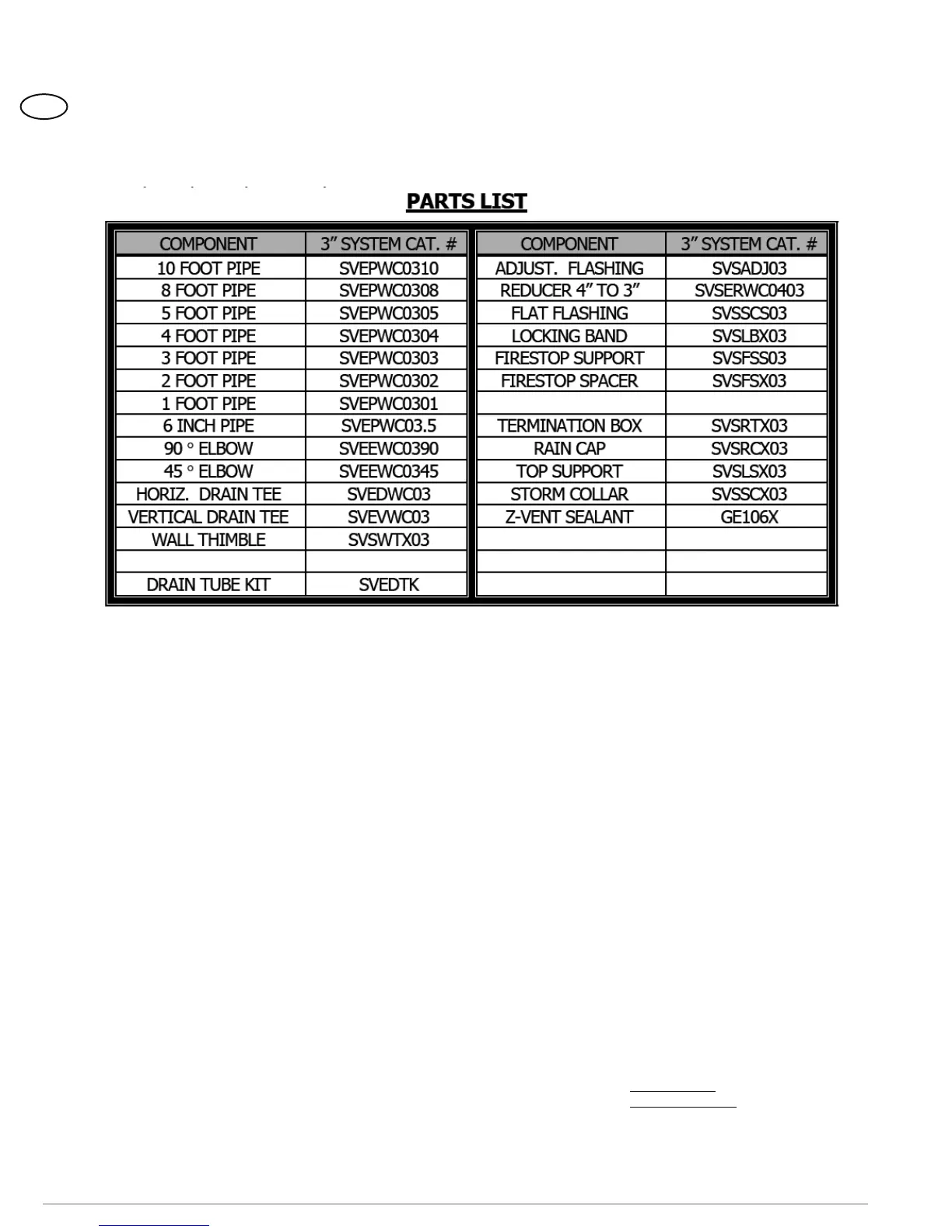
TERMINATION HOOD
SVSHTX03