14-6
Points Operation
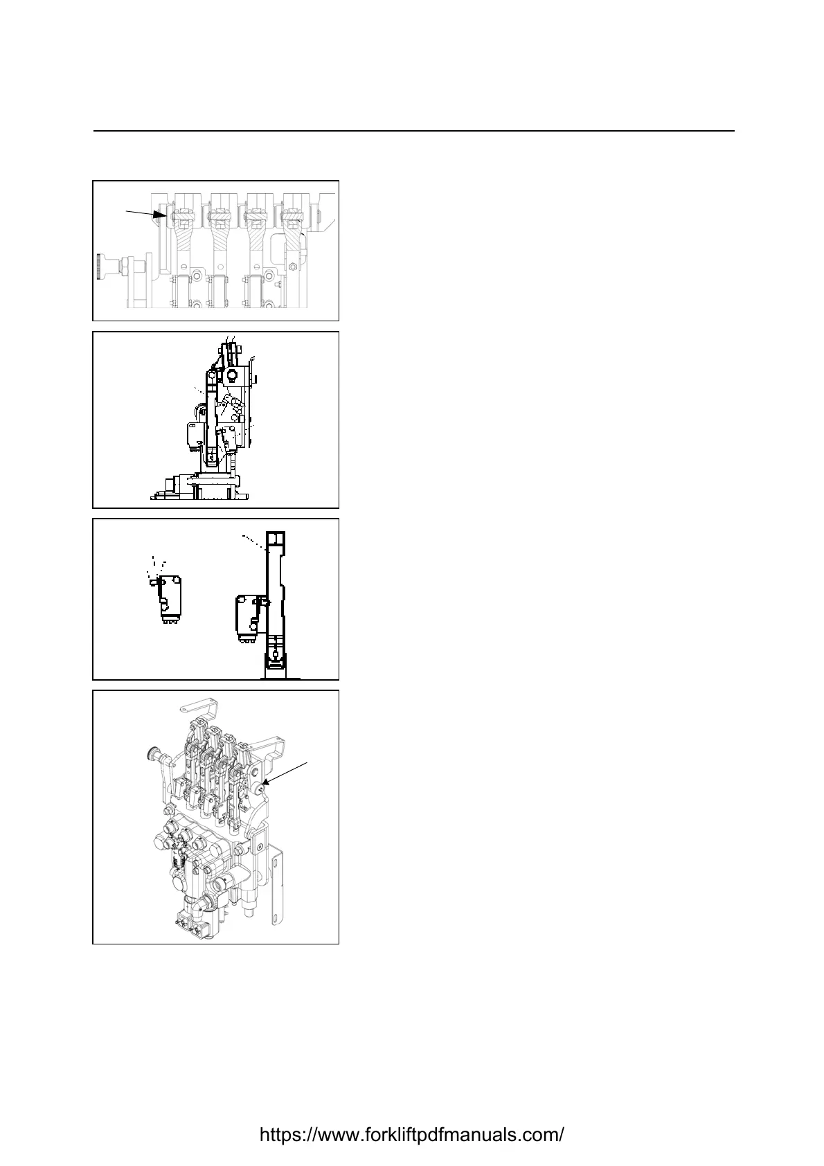
[Point 1]
Disassembly:
Remove the pin A of each lever
Microswitch adjustment:
After the installation perform the following adjustments:
1. Keep the microswitch in rest position as shown in the
drawing according to the following points:
• The castor of the microswitch has to be in contact with the
surface of the command rod
• The microswitch lever has to be in contact with the push
button of the microswitch, without activating it
2. Tighten the microswitch in order to have the possibility to
move it on the button hole of the support.
3. Adjust the microswitch position in order to activate it to
the minimum stroke of the microswitch lever and by
releasing the latter the microswitch has to return in rest
position. The activation of the microswitch could be
detected:
• by eyes (by checking the angular stroke on the
microswitch lever)
• by ears (by listening to the closing of the microswitch
contacts)
• by multimeter (by checking the microswitch output signals)
4. Tighten the microswitch screws with a tightening torque
of 0.39-0.59 Nm
Adjustment (lifting potentiometer P):
after installation, adjust the lifting potentiometer
• assemble the potentiometer on the control valve
• connect an analogic multimeter, setted it at least on the
range 10kOhm, to the potentiometer connector pins, in the
following way: the red terminal (+) to the pin 2; the black
terminal (-) to the pin 3
• move the lifting lever up to the lifiting micro turns off; the
value on the multimeter must be 5 kOhm
• After the installation perform the lifting potentiometer
adjustment (see chapter 3: Display)
CONTROL ROD
LEVER
PUSH BUTTON
CASTOR
https://www.forkliftpdfmanuals.com/