2-20
REMOVAL • INSTALLATION
Before starting, disconnect the battery plug and measure the voltage across (+) and GND; if
voltage is present, fit a 100Ω resistance between (+) and GND to discharge the condensers.
Removal procedure
1. Remove the boot
2. Move the seat forward
3. Move the lever of the mechanic control valve forward (only with mechanic control valve version)
4. Open the battery cover
5. Disconnect the battery plug
6. Disconnect the wiring and the power cables of the main controller
7. Remove the logic unit
Installation procedure
The reassembly procedure is the reverse of the disassembly procedure.
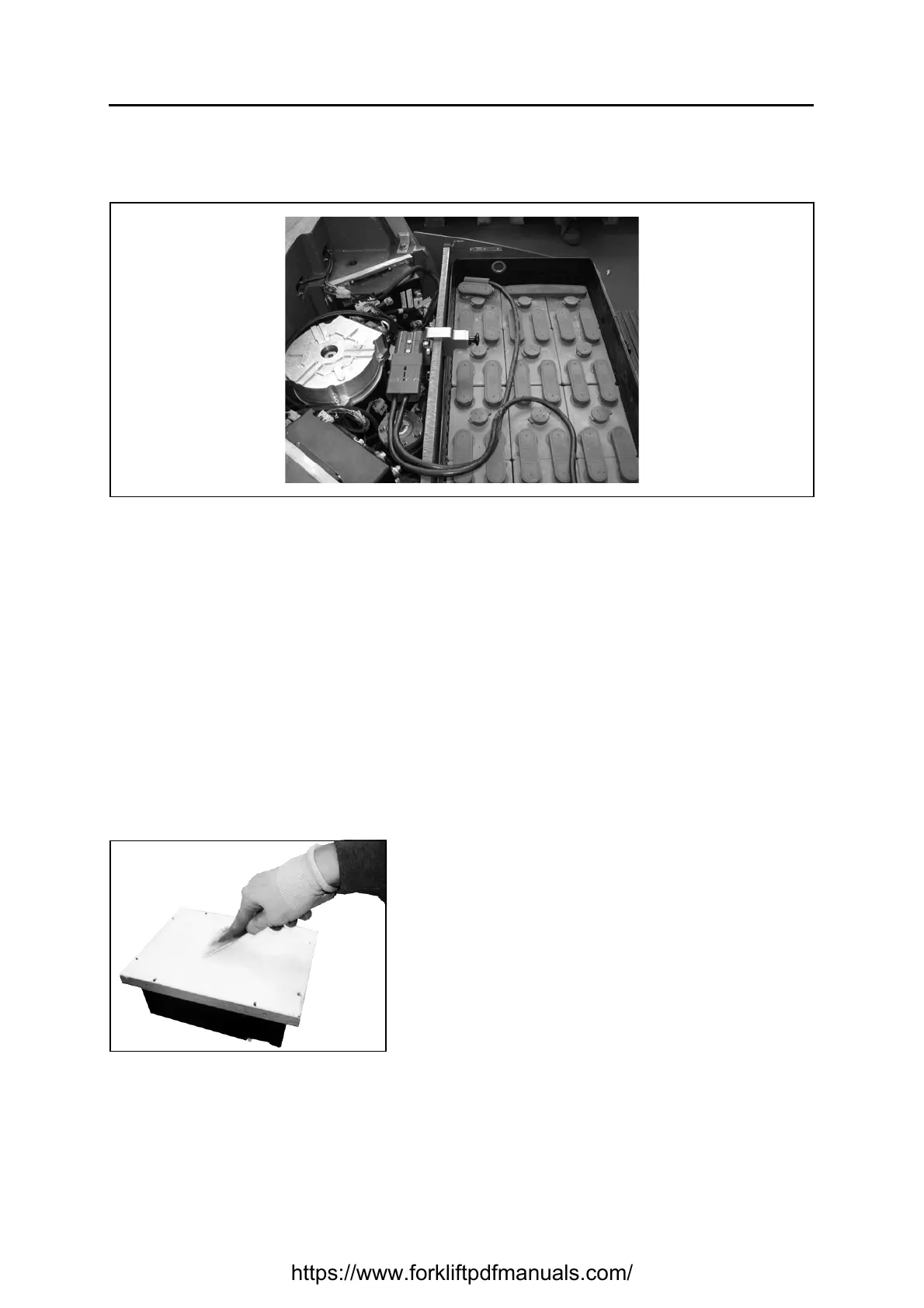
Whenever one of the logic units has been disassembled, rimember to restore the thermic transmission
paste (Silicone Heat Transfer Compound Plus) layer between the logic unit and the heat radiant
structure, the counterweight. This white colour product consisting of powdered metal oxides (ceramic)
compounded in a silicone oil base. It must be spreaded in a thiny film on one of the two assembly
surfaces and then you can proceed to the reassembly.
Remarks:
For thermic transmission paste (Silicone Heat Transfer
Compound Plus) see Service Tools List
https://www.forkliftpdfmanuals.com/