fittings.
Be
sure
eccentric
bushings
are
positioned
as
marked.
b.
Install
bolts,
spacers,
and
nuts
to
secure
upper
and
lower
ends
of wing
strut
to
wing and
fuselage
fit-
tings.
c.
Route
flap
and
aileron
cables,
using
guide
wires.
(See note
in
paragraph
4-4.
)
d. Connect:
1.
Electrical
wires
at
wing
root
disconnects.
2.
Fuel
lines
at
wing
root.
(Refer
to
precau-
tions
outlined
in
paragraph
12-3.
)
3.
Pitot
line
(if
left
wing
is
being
installed).
4. Wing
leveler
vacuum
tube, if
installed,
at
wing
root.
e.
Rig
aileron
aystem.
(Section 6. )
f.
Rig
flap
system.
(Section 7. )
g.
Refuel
wing
tank
and
check
for
leaks.
(Refer
to
precautions
outlined
in
paragraph
12-3.
)
h. Check
operation
of wing
tip
and landing
and
taxi
lights.
(thru
1970 Models).
i.
Check
operation
of
fuel
gage.
j.
Install
wing
root
fairings.
NOTE
Beginning with 1972 Models, a
extruded
fillet
sealant
(576.1
Permagum:
Presstite
Engin-
eering
Company) of
equivalent
is
applied
be-
tween
cabin
top
skin
and wing
skin,
also
across
top
of
lower
strut
fitting
at
skin
cutout. Gap
between
windshield
and
wing
leading
edge
is
sealed
with
(Polyken
230
or
Polyken
231;
Kendall-Polyken
Division,
Tuck
92T,
Techni-
cal
Tape
Corporation)
or
equivalent.
NOTE
Be
sure
to
insert
soundproofing
panel
in
wing
gap,
if
such
a
panel
was
installed
originally,
before
replacing
wing
root
fairings.
k.
Install
all
wing
inspection
plates,
interior
panels
and
upholstery.
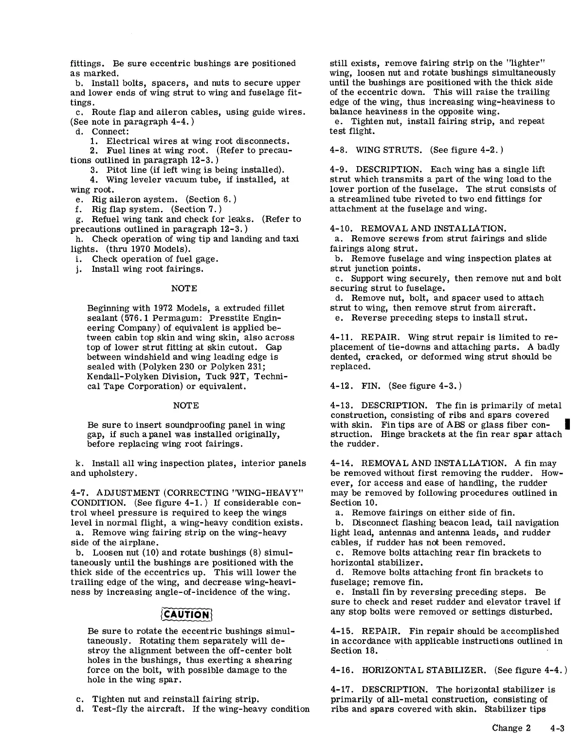
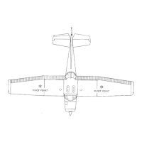
4-7.
ADJUSTMENT (CORRECTING "WING-HEAVY"
CONDITION.
(See
figure
4-1.)
If
considerable
con-
trol
wheel
pressure
is
required
to
keep
the
wings
level
in
normal
flight, a wing-heavy condition
exists.
a.
Remove wing
fairing
strip
on
the
wing-heavy
side
of
the
airplane.
b.
Loosen
nut (10)
and
rotate
bushings
(8)
simul-
taneously
until
the
bushings
are
positioned
with
the
thick
side
of
the
eccentrics
up.
This
will
lower
the
trailing
edge of
the
wing,
and
decrease
wing-heavi-
ness
by
increasing
angle-of-incidence
of
the
wing.
Be
sure
to
rotate
the
eccentric
bushings
simul-
taneously.
Rotating
them
separately
will
de-
stroy
the
alignment
between
the
off-center
bolt
holes
in
the
bushings,
thus
exerting
a
shearing
force
on
the
bolt,
with
possible
damage
to
the
hole
in
the
wing
spar.
c.
Tighten
nut
and
reinstall
fairing
strip.
d.
Test-fly
the
aircraft.
If
the
wing-heavy
condition
still
exists,
remove
fairing
strip
on
the
"lighter"
wing,
loosen
nut
and
rotate
bushings
simultaneously
until
the
bushings
are
positioned
with
the
thick
side
of
the
eccentric
down.
This
will
raise
the
trailing
edge
of
the
wing,
thus
increasing
wing-heaviness
to
balance
heaviness
in
the
opposite wing.
e.
Tighten
nut,
install
fairing
strip,
and
repeat
test
flight.
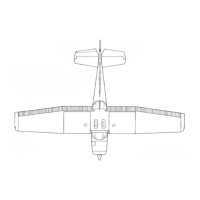
4-8.
WING
STRUTS. (See
figure
4-2.)
4-9.
DESCRIPTION.
Each
wing
has
a Single
lift
strut
which
transmits
a
part
of
the
wing load
to
the
lower
portion
of
the
fuselage.
The
strut
consists
of
a
streamlined
tube
riveted
to
two
end
fittings
for
attachment
at
the
fuselage
and
wing.
4-10.
REMOVAL AND INSTALLATION.
a.
Remove
screws
from
strut
fairings
and
slide
fairings
along
strut.
b.
Remove
fuselage
and wing
inspection
plates
at
strut
junction
points.
c.
Support wing
securely,
then
remove
nut and
bolt
securing
strut
to
fuselage.
d. Remove nut,
bolt,
and
spacer
used
to
attach
strut
to
wing,
then
remove
strut
from
aircraft.
e.
Reverse
preceding
steps
to
install
strut.
4-11.
REPAIR. Wing
strut
repair
is
limited
to
re-
placement
of
tie-downs
and
attaching
parts.
A badly
dented,
cracked,
or
deformed
wing
strut
should
be
replaced.
4-12.
FIN. (See
figure
4-3.)
4-13.
DESCRIPTION.
The
fin
is
primarily
of
metal
construction,
conSisting of
ribs
and
spars
covered
with
skin.
Fin
tips
are
of ABS
or
glass
fiber
con- I
struction.
Hinge
brackets
at
the
fin
rear
spar
attach
the
rudder.
4-14.
REMOVAL AND INSTALLATION. A fin may
be
removed
without
first
removing
the
rudder.
How-
ever,
for
access
and
ease
of
handling,
the
rudder
may
be
removed
by following
procedures
outlined
in
Section
10.
a.
Remove
fairings
on
either
side
of fin.
b.
Disconnect
flashing
beacon
lead,
tail
navigation
light
lead,
antennas
and
antenna
leads,
and
rudder
cables,
if
rudder
has
not
been
removed.
c.
Remove
bolts
attaching
rear
fin
brackets
to
horizontal
stabilizer.
d. Remove
bolts
attaching
front
fin
brackets
to
fuselage;
remove
fin.
e.
Install
fin
by
reversing
preceding
steps.
Be
sure
to
check
and
reset
rudder
and
elevator
travel
if
any
stop
bolts
were
removed
or
settings
disturbed.
4-15.
REPAIR.
Fin
repair
should
be
accomplished
in
accordance
with
applicable
instructions
outlined
in
Section
18. .
4-16.
HORIZONTAL STABILIZER. (See
figure
4-4.)
4-17.
DESCRIPTION.
The
horizontal
stabilizer
is
primarily
of
all-metal
construction,
conSisting of
ribs
and
spars
covered
with
skin.
Stabilizer
tips
Change 2
4-3