8. Battery, Charging System
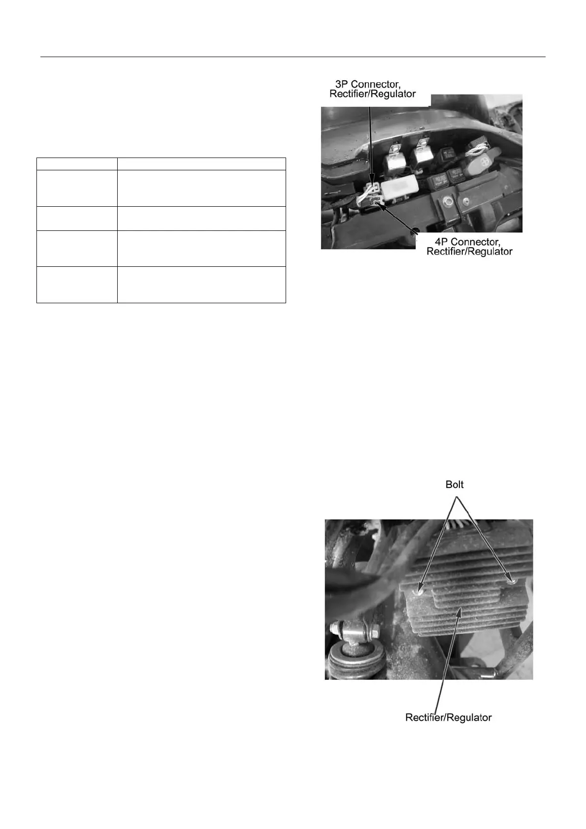
Check the connector terminals for loosening,
bending, rust or come-off.
Check the following items of the main cable terminals of
the two rectifier connectors:
Item Result
Battery wire
(red)
There should be voltage between
red terminal (+) and frame body
earth wire
Earth wire
(green)
Green terminal must be connected
with frame body earth wire
Charging coil
(yellow, yellow,
yellow)
Resistance between yellow
terminals is: 0.2-0.3Ω (at 20℃)
Ignition switch
lead wire
(black)
Black lead wire must be
connected with black terminal.
Installation:
Reverse the removal procedure for installation.
Note:
Wires, hoses and cables should be routed properly.
(→Charpter1)
8-7