3.3.1.1 USB port
The USB port on the CONTROL board is dedicated to the firmware update of the X1 unit. Do not use it for any other purpose. For
more information on unit firmware update, please refer to chapter 5 of this manual.
3.3.1.2 Push-buttons
Two push-buttons allow access to four functions, depending when they are pushed. Detailed information on that topic is provided in
chapter 4 (Operation) of this manual.
3.3.2 POWER SOURCE board
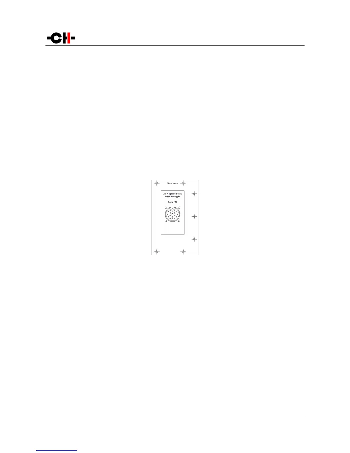
As an X1 can be used to power one or two CH Precision units, it can be fitted with one or two Power source boards. Each board has
its own set of discrete regulators for analog and digital voltage rails. The following drawing shows the layout of the back panel of
the POWER SOURCE board:
POWER SOURCE board back panel layout
3.3.2.1 Power connector
The interface between an X1 and a CH Precision unit is handled by the Power Link Cable, plugged to the 19-poles connector at both
ends.
Make sure both X1 and X1-powered unit are turned off completely (Power on/off switch in the off position) before connecting the
two units together. Insert the Power Link Cable plugs and secure them by fully tightening their outer ring.
Then both units can then be switched on (Power on/off switch in the on position). They will remain in standby until the X1-powered
device is taken out of standby (by pushing its inner encoder, or from its remote control).
The X1's wake up and standby operations are automatically taken care of by signals exchanged between the units through the
Power Link Cable, so no user action is required on the X1 once its power switch is in the on position.
Rev 2.1 X1 User Manual 15