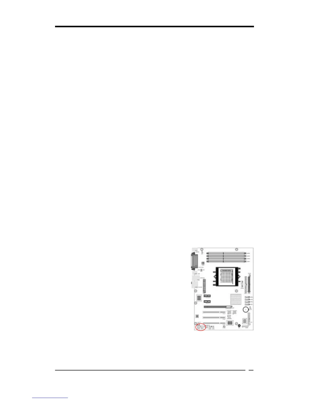
2. P-LED (Power LED Connector):
The power indicator LED shows the system's power status. It is important to pay
attention to the correct cable and pin orientation (i.e. Be careful not to reverse the
order of these two connectors.)
3. G-BTN (Green Button Switch):
Some ATX cases provide a Green button switch, which is used to put the system in
Suspend mode. While in Suspend mode, the power supply to the system is reduced
to a trickle, the CPU clock is stopped, and the CPU core is in its minimum power
state. The system is activated whenever the keyboard or mouse is touched. The
system will resume in various ways as defined by Power Management Setup screen
in BIOS.
4. RESET (System Reset Switch Connector):
This connector should be connected to the reset switch on the front panel of the
system case. The reset switch allows you to restart the system without turning the
power off.
5. SPEAKER (Speaker Connector):
This 4-pin connector connects to the case-mounted speakers.
6. HD-LED (IDE - Activity LED Connector):
The IDE- activity LED lights up whenever the system reads/writes to the IDE
devices.
CN2/2A (CD-IN):
These connectors are responsible for connecting the CD-ROM to receive sound
signals.