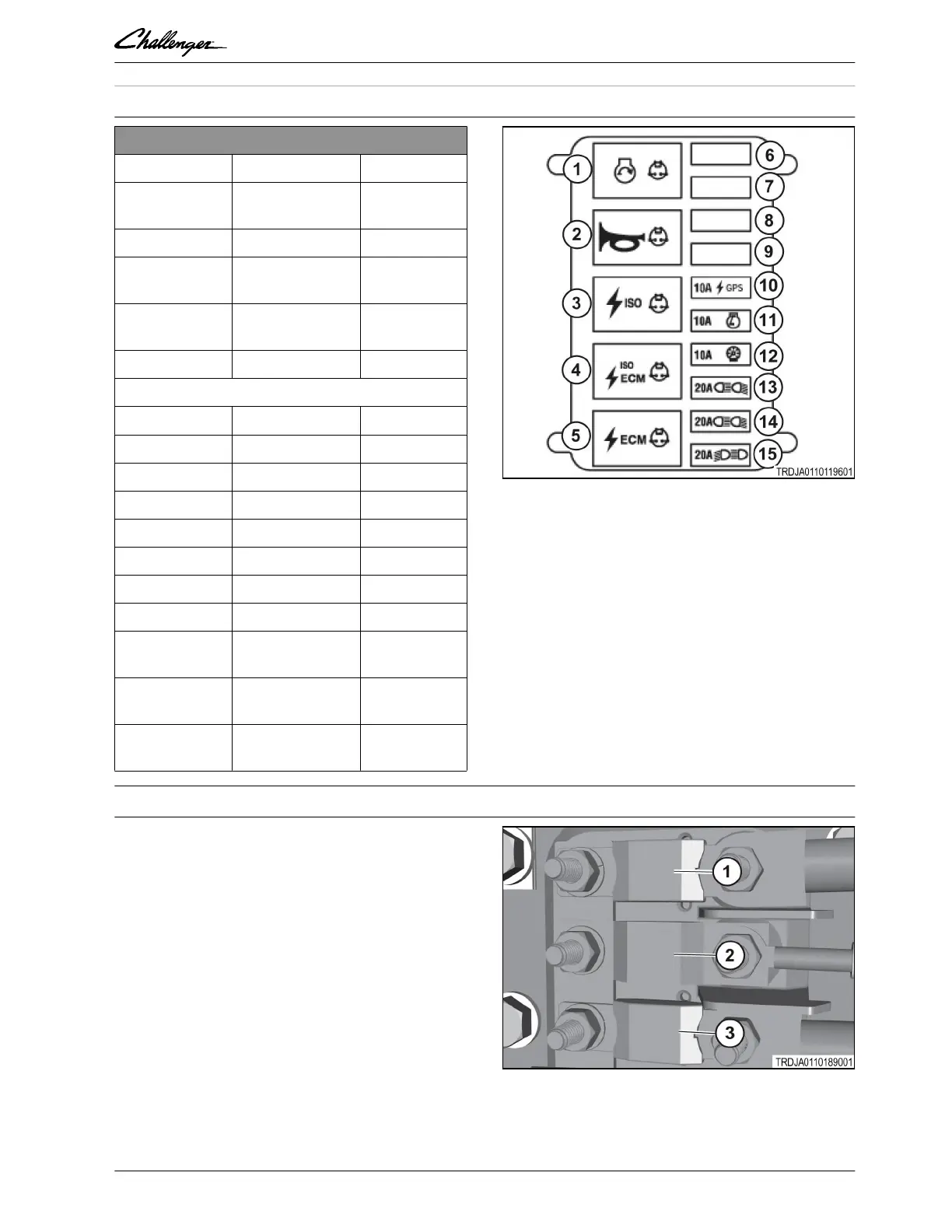
1.8.5 Fuse relay block two
Fuse / relay block two
Item Relay Description
1 35 Amp Neutral start
relay
2 35 Amp Horn relay
3 35 Amp ISO power
relay
4 35 Amp ISO ECU
relay
5 35 Amp ECU relay
Fuse / relay block two - ECU relay power
Item Fuse Description
6 Not used
7 Not used
8 Not used
9 Not used
10 10 Amp GPS
11 10 Amp Armrest
12 10 Amp Dash
13 20 Amp Bottom light
module
14 20 Amp Bottom light
module
15 20 Amp Top light
module
GUID-DF07ED36-70A1-4182-B3B4-FA2D54DD9891-high.jpg [High]
Fig. 30
1.8.6 Main fuse
The two main fuses for the cab power and the
alternator are located inside the frame rail.
(1) Alternator, 300 Amps
(2) ECM, Starter relay and Auxiliary Relay, 100
Amps
(3) Cab stud, 175 Amps
GUID-E9FF3683-3810-4339-9D81-F1C3CD04A41C-high.jpg [High]
Fig. 31
GUID-676FEAA6-B2A0-4E2F-B598-A275D350B6E5 [V1]
GUID-9D9F8C22-EB2B-4E35-BC3C-FCB6EE11BE04 [V3]
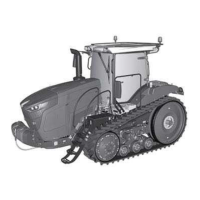
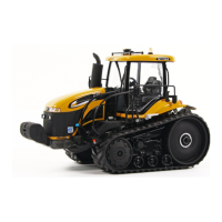
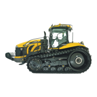
1. General
Rubber Track Tractor 1-35
79036614D
 Loading...