10. Replace the chocks at the front and rear of the tracks.
11. Add the correct oil to the threaded hole (1) in the outer hub until the oil level reaches bottom of the
threaded hole. Approximately 1.4 L
12. Install plugs in both the inner and the outer hubs.
1.9.3 Do a check of the oil level for the idler wheel and the mid roller wheel hubs
NOTE: Inspect the oil level frequently if the machine is operated in extremely wet or muddy conditions.
Change the oil every 400 hours under these conditions.
1. Park the machine on a hard level surface.
2. Place the chocks at the front and the rear of
the tracks.
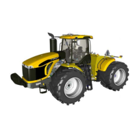
3. Clean the sight glass (1) with a soft moist
cloth. Keep the oil level between the lower
1/3 and the upper 1/3 of the sight glass. If
necessary, add the oil through the fill/drain
plug (2). Add oil that meets the requirements
described in the refill capacities section.
GUID-C5426C6E-C1A8-45BD-8818-BE91942BAD5C-high.jpg [High]
Fig. 36
1.9.4 Change the oil on the idler and the mid roller wheel hub
NOTE: Dispose of all fluids according to local regulations and mandates.
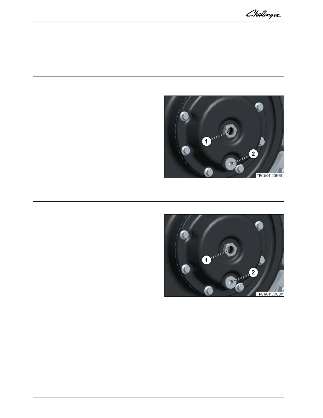
1. With the machine on a hard level surface,
drive forward or rearward slightly, to locate
fill/drain plug (2) at six o'clock position.
2. Place the chocks at the front and the rear of
the tracks.
3. Clean the area around the fill/drain plug.
4. Remove the plug (2) and allow the oil to drain
into an approved oil container.
5. Remove the wheel chocks and drive the
machine forward or rearward slightly until the
threaded hole is approximately at twelve
o'clock position.
6. Replace the chocks at the front and the rear of the tracks.
7. Add the correct oil until the oil level reaches the mid point on the sight glass (1).
8. Install the plug (2).
GUID-C5426C6E-C1A8-45BD-8818-BE91942BAD5C-high.jpg [High]
Fig. 37
1.9.5 Track and undercarriage inspection
The rubber track carcass has many layers of cable, similar to the cables used in automotive tires. The most
important set of cables are located about 8 mm (0.3 in) beneath the inside surface of the track. This set of
cables, called the zero degree cables (1), with stands track tension. Other sets of cables, called the breaker
cables (2) are located between the zero degree cables and the outside surface of the track. The cables are
in dierent angles to give lateral support and to protect the zero degree cables.
GUID-ACBFA2E4-4929-411A-8DA1-BEF4D8B94A92 [V3]
GUID-705C9C69-9288-4634-B31D-778D56E64361 [V3]
GUID-639A267F-17FF-4112-AF27-19F296421DC6 [V2]
1. General
1-38 Rubber Track Tractor
79036614D
 Loading...