23
Installation
STEP 13 Install the Protector System
®
(continued)
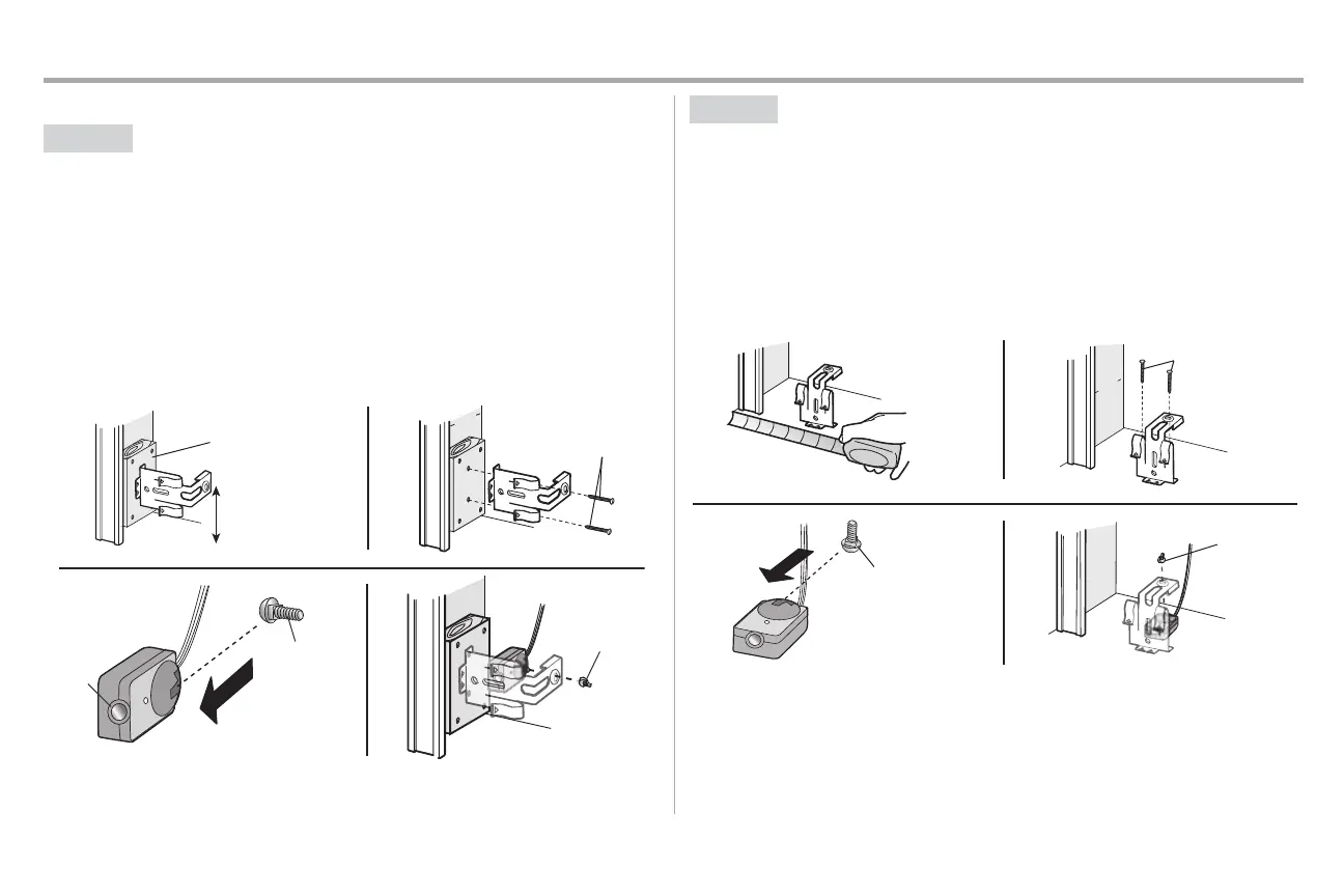
OPTION B WALLINSTALLATION
If additional clearance isneeded an extension bracket (not provided) or wood blockscan be used. Make
sure each bracket has the same amount of clearance so they will align correctly.
1. Position the sensor bracketagainstthe wall with the curved arms facing the door. Make sure
there is enough clearance for the beam to be unobstructed. Mark holes.
2. Drill 3/16 inch pilotholes for each sensor bracketand attach the sensor brackets to the wall
using lag screws(not provided).
3. Slide the carriage bolt into the sloton each sensor.
4. Insert the boltthrough the hole in the sensor bracketand attach with the wing nut. The lenses
on both sensorsshould pointtoward each other.Make sure the lensis not obstructed by the
sensor bracket.
(Not provided)
No more than
6 inches (15 cm)
1
2
Inside
G
arage
Wall
(Not provided)
Lens
Carriage Bolt
1/4"-20x1/2"
Wing Nut
1/4"-20
3
4
OPTION C FLOORINSTALLATION
Use an extension bracket(not provided) or wood block to raise the sensor bracketif needed.
1. Carefully measure the position of both sensor bracketsso theywill be the same distance from
the wall and unobstructed.
2. Attach the sensor brackets to the floor using concrete anchors (not provided).
3. Slide the carriage bolt into the sloton each sensor.
4. Insert the boltthrough the hole in the sensor bracketand attach with the wing nut. The lenses
on both sensorsshould pointtoward each other.Make sure the lensis not obstructed by the
sensor bracket.
I
nsid
e
G
arage
Wa
l
l
(Not provided)
1 2
Carriage Bolt
1/4"-20x1/2"
Wing Nut
1/4"-20
3
4