12
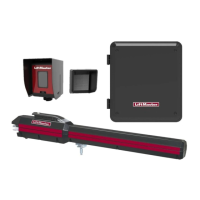
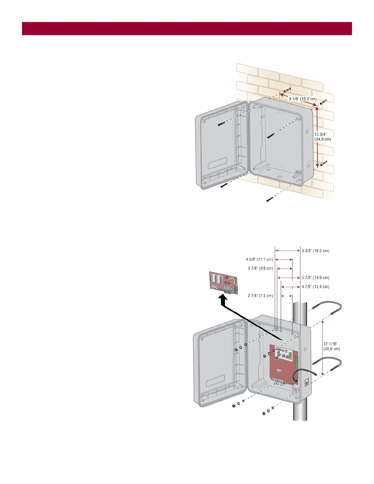
Step 3 Install the Control Box
Standard Control Box
The control box MUST be mounted within 5 feet (1.52 m) of the gate
operator. Mount the control box as high as possible for best radio
reception. Make sure the control box is level.
NOTE: The expansion board DOES NOT need to be removed for a wall or
column mount installation.
1. Remove the screws and open the control box.
2. Disconnect the "Main Board" connector from the expansion board.
3. Remove the expansion board by removing the screws.
4. Select the mounting holes (according to your application) and
remove the knockouts using a screwdriver and hammer.
5. Secure the control box to mounting surface.
A.
Wall or Column: Use the provided screws (4).
B.
Post: Use U-bolts and rubber washers (not provided) to ensure
a watertight seal. Make sure the U-bolts do not protrude more
than 3/4 inch from the control box because this can short the
control board.
6. Reinstall the expansion board and connect the "Main Board"
connector to the expansion board.
INSTALLATION