A
38
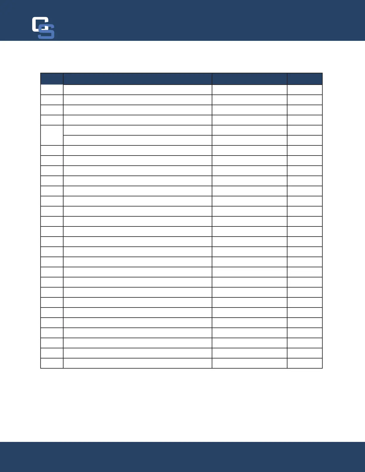
REF DESCRIPTION PART NO. QTY
1 Piston Assembly Final Rinse 20009X231 1
2 10-24 X 3/4” Screw SST 20001X001 5
3 Seal and Spacer Kit 20561X253 1
4 End Spacer 20001X234 1
5
Flow Control Button 5.0 GPM 20251X272 1
Flow Control Button 7.0 GPM 20251X273 1
6A DLFC Housing 20017X251 1
7 Drain Line Hose Barb 90 ° Elbow 20017X266 1
8 Brine Valve 20009X225 1
9 BLFC Assy. SST 20009X228 1
10 BLFC Ferrule 3/8” 20251X305 1
11 Plug 3/8” 20009X005 1
12 10-24 X 3/4” Screw SST 20001X226 2
13 3/8” Push Lock Plug 20009X010 1
14 Injector Cap 20009X001 1
15 Injector Seal 20001X224 1
16 Injector Assy. #1 White 20017X219 1
17 Injector Screen 20001X222 1
18 Injector Plug & O-Ring Assy 20001X217 1
19 Tank / Valve O-Ring 20015X043 1
20 Dist. O-Ring 20561X204 1
21a Meter Assembly 20017X203 1
21b Meter Plug w/ O-Ring 20017X201 1
22 3/8” Push Lock 90 ° Elbow GA-Q0620626BV 1
23 Air Injector Check Assy 20017X010 1
24 Injector, White 20017X219 1
25 Check Valve 20017X009 1
26 1/4” NPT Cap 20018X035 1
SIDE VALVE
Chandler Systems
38