202-01-4 Driving Axle 202-01-4
INSTRUCTION AND OPERATION (Continued)
BENNI MINI
The Working Principle of the Driving Axle
The torque is transmitted from the engine to the wheels
through the driving axle.
In order to adapt to the upper and lower motion of the
wheel and the engine, the driving axle is required to run
in various lengths and angles.
The Treatment of the Driving Axle
Note: The clipping of the driving axle by the constant
speed universal joint is forbidden.
When dismounting, installation, disintegrating and
assembling it should be cautious. The following
instructions should be observed.
– When the driving axle is dismounted, never push or
pull the constant speed universal joint
– The working angle of the constant speed universal
joint can not be more than 22.5 degrees.
– Check whether the polished surface and the spline
are damaged.
– It is forbidden that the dust shield is contacted with
the sharp edge and the hot engine or the exhaust
system.
– Do not drop the driving axle, otherwise, it could
cause the inner damage of the dust shield, which
can not been seen from outside.
– When other parts and components are installed,
never use the driving axle as the prying tool. The
driving axle can not be hung at will.
– The hitting of the universal joint cage from
outside can cause the damage of the constant
speed universal joint.
Front wheel balancing
Warning: When the vehicle is lifted above the
ground completely, using the portable wheel
balancing device can cause the damage of the
constant speed universal joint or the dust
shield, and this is caused due to the fact that
the bending angle of the universal joint is
overlarge.
When the portable wheel balancing device is used, the
hand pushing type jack can be positioned under the
lower cross arm. This can prevent the overlarge of the
bending of the universal joint when the vehicle is lifted.
If the conditions are satisfied, it is better to dismount
the wheels, which should be performed on the fixed
wheel balancing device.
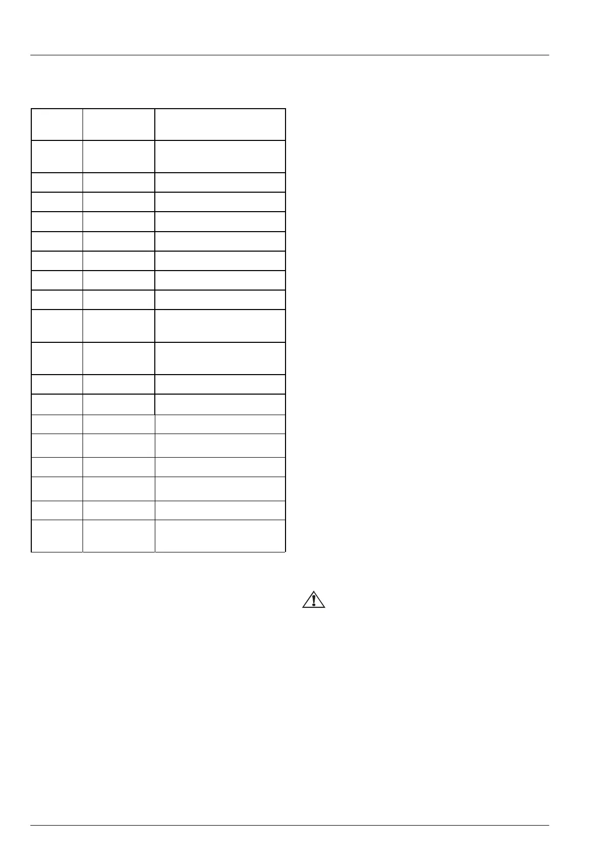
Serial
Number
Parts
Number
Designation tion
1
2203110-K
01
Fixed end ball cage
universal joint
2 2203143-K01 Large nip
3 2203151-K01 Dust shield
4 2203144-K01 Small clip at the outer end
5 2203133-K01 Left shaft lever
6 2203141-K01 Small clip at the inner end
7 2203152-K01 Dust shield
8 2203142-K01 Large clip at the inner end
9 2203120-K01
Movable three-pin type
universal joint
10
2203110-K01
Fixed ball cage universal
joint
11 2203143-K01 Large clip
12
2203151-K01 Dust shield at the outer end
13 2203144-K01 Small clip at the outer end
14 2203233-K01 Right shaft lever
15 2203141-K01 Small clip at the inner end
16 2203152-K01 Dust shield at the inner end
17 2203142-K01 Large clip at the inner end
18
2203220-K01
Three-pin type movable
universal joint
 Loading...