F10 Installation Manual Rev. *60 11 of 71
System Diagrams
The F10 system uses an antenna assembly comprised of wire coils wrapped around ferrite material
tiles. Antennas
are enclosed in PVC casings for strength and protection from environmental factors.
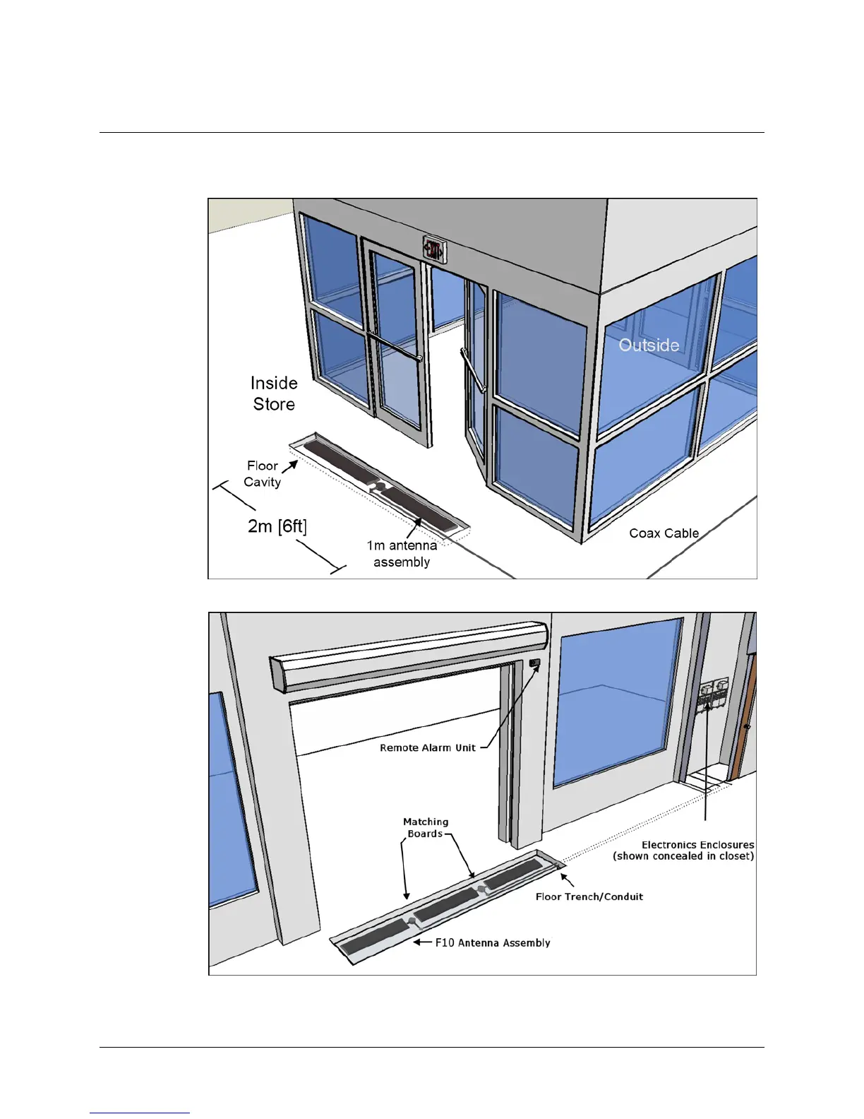
Figures
1.4 and 1.5 show common installation coverage widths: 2m and 3m [6 and 9ft respectively].
Figure 1.4 Typical F10, 2 Meter Installation
Figure 1.5 3m [9ft] Installation Layout with Component Names