F10 Installation Manual Rev. *60 20 of 71
Common Wider Floor Cuts
It is possible to create a wider system by combing either of the smaller two floor kits (refer to
Figures 3.1 and 3.2 above). For example, to cover a 3m mall opening, a 1m and 2m kit are ordered.
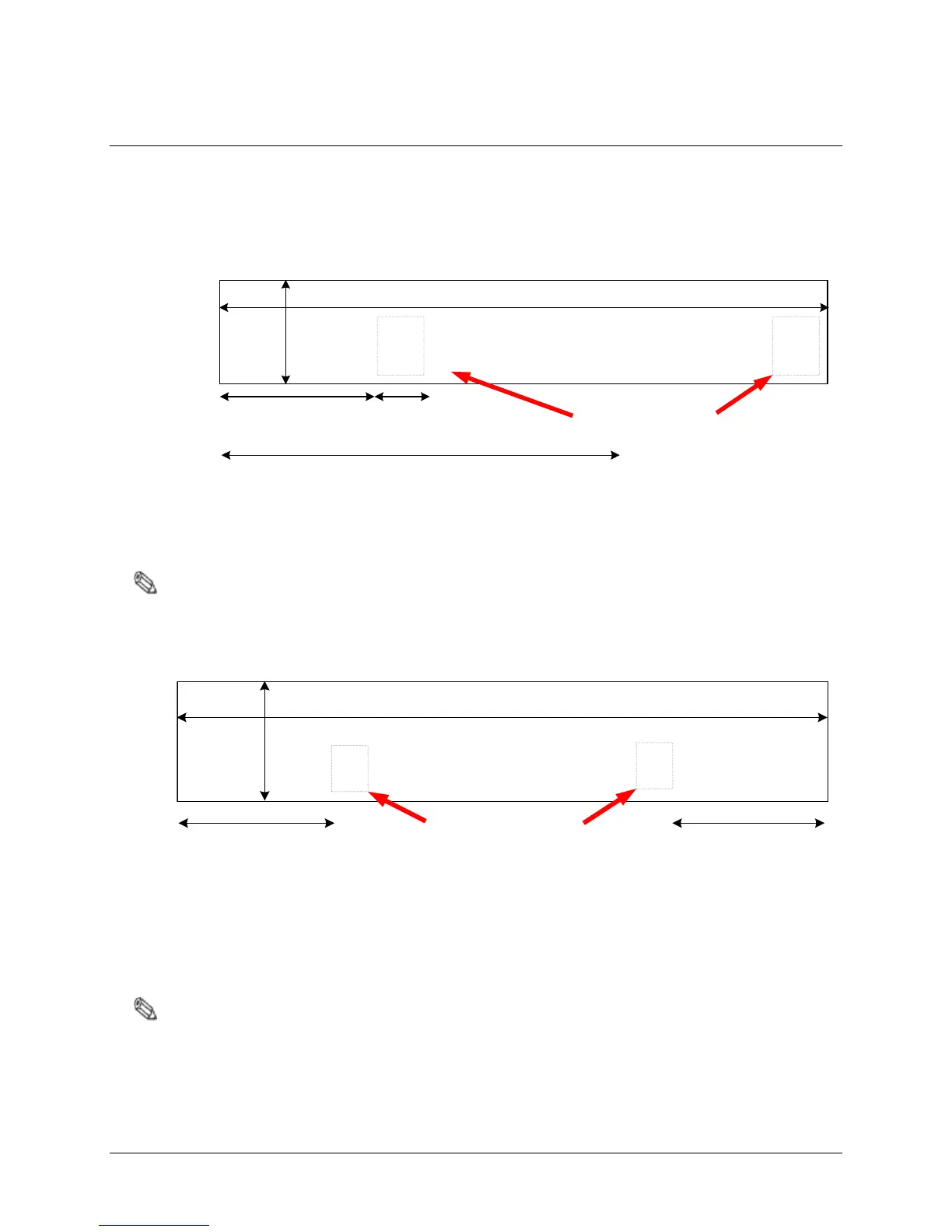
Figure 3.6 below shows exact dimensions of the trough (floor cuts) when the F10, 1 meter and 2
meter systems are combined. Figure 3.7 shows two (2) F10, 2 meter systems installed side-by-side.
354.5cm [139.6in]
Matching Board
Locations
117.5cm
[46.27in]
224.2cm [88.3in]
35.5cm
[14in]
21.8cm
[8.6in]
Figure 3.6 2m and 1m System for 3m Opening
Note: Figures are Not Drawn to Scale
461cm [181.5in]
Matching Board
Locations
35.5cm
[14in]
117.5cm
[46.27in]
117.5cm
[46.27in]
Figure 3.7 Side-by-Side 2m Systems for 4m Opening
Note: The Impedance Matching Board placement for the F10, 2 meter system is between the assemblies.
For the F10, 1 meter system, board placement is beside the antenna assembly. The ENT Tubing
(with coax cable) can be routed in any direction from antenna to electronics. A minimum spacing of 2”
between the antenna and tubing is required.