F10 Installation Manual Rev. *60 18 of 71
Caution: Prevent uneven stress on the fragile electronic components inside the assembly by ensuring the
floor trough is smooth and level. Fill in uneven areas or gaps with leveling sand or concrete filler.
F10, 1 Meter and 2 Meter Floor Cuts
Installing the F10 antenna assembly in an existing store requires a trough to be cut in the floor.
If the site is under construction, it is easier to mold the system into the floor (explained above).
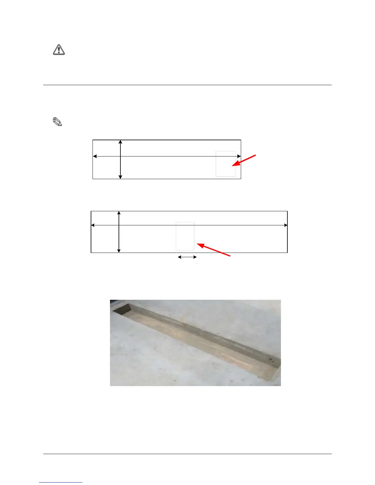
These diagrams include details on the size of the trough cuts required for each configuration.
Note: Figures are Not Drawn to Scale
127.6cm [50.25in]
35.5cm
[14in]
F10 Matching
Board Location
Figure 3.1 Top View of F10, 1 Meter Floor Cut
F10 Matching
Board Location
21.8cm [8.6in]
234.5cm [92.33in]
35.5cm
[14in]
Figure 3.2 Top View of F10, 2 Meter Floor Cut
Figure 3.3 Trough for the 2 Meter assembly