MAN250/04 Page 4
INSTALLATION
LOCATION
Mount the controller cabinet as shown in Figure 2 on a wall in a
secure location:
• more than 10' (3 m) away from the water edge to
comply with electrical code requirements,
• if possible, not more than 10' (3 m) of the main
recirculation line or of the bypass line. The sensors
come with standard 10-foot (3-m) cables. If needed,
you can order 25 or 50-ft BNC extension cables from
your dealer.
• not exposed to direct sunlight,
• easily accessible to maintenance personnel,
• if possible in a separate room, or in a well- ventilated
room as far away as possible from corrosive chemicals
and storage tanks,
• at a safe distance from power transformers, pump
motors or high voltage power lines
• safe from unauthorized access or vandalism.
SENSOR INSTALLATION
Save the sensor caps for storage or shipping of the sensors.
When in storage or shipping, add salt water in the cap to keep the
sensors from drying out. During winter, store the sensors above
freezing temperature.
The sensors can be mounted three different ways:
• directly on the main recirculation line (Figure 2) (2 in.
pipe only),
• on a 1/2 in. bypass line as shown Figure 3,
• even better, in a sensor cell mounted on the bypass line
(Figure 5).
MAIN LINE INSTALLATION
On smaller installations (2 “ pipe diameter), the sensors can be
mounted directly on the main recirculation line (Figure 2).
Use only the 2x2x1/2 in. SST reducing tees without reducers
(Figure 3). Do not install the sensors near an elbow or a
constriction where there might be excessive turbulence.
Install the tees after the pump and filter. Insert the sensor tip
down so that the tip is about 1/4 inch (1 cm) in the water. The
sensors should be readily accessible for servicing but not
exposed to physical damage.
Tighten the compression fitting by hand only to avoid breaking the
internal glass tube in the sensors. Do not use a wrench!
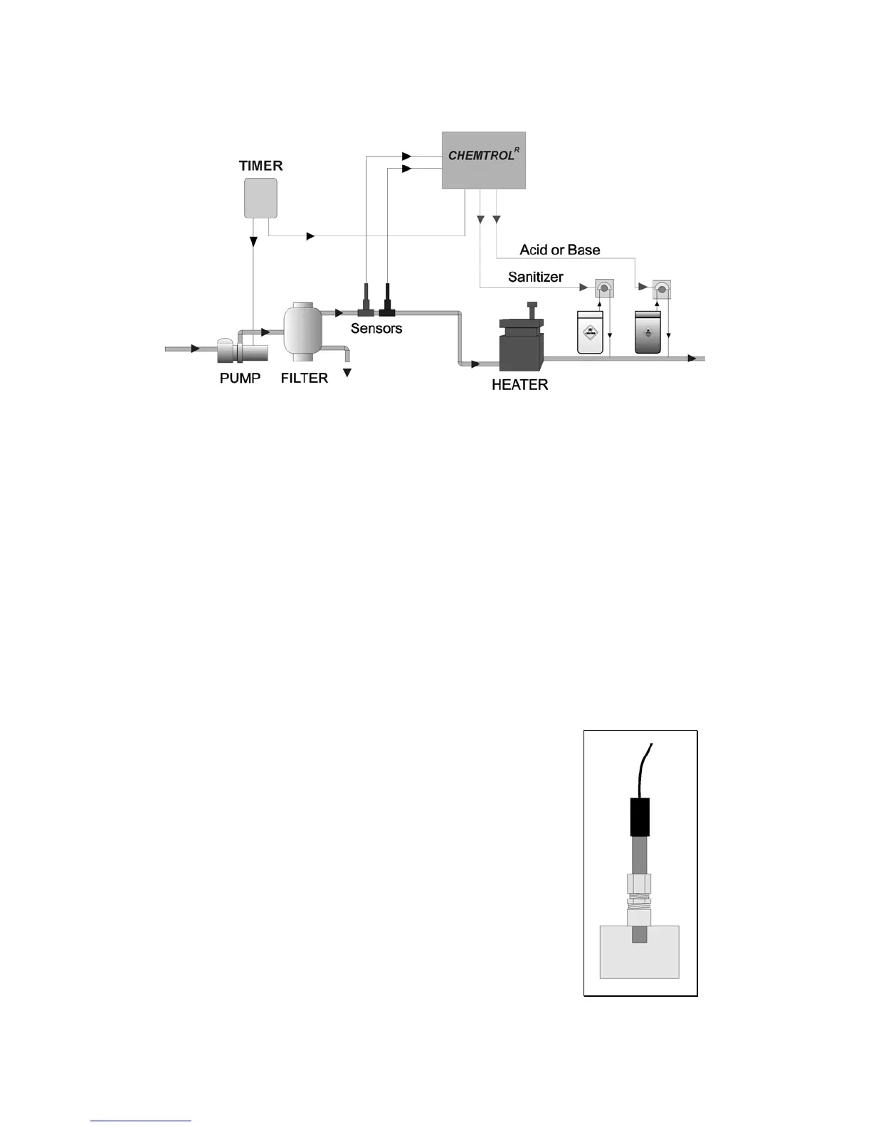
Figure 2 - Installation with Sensors on Main Line
Figure 3 - Sensor in PVC Tee
 Loading...