MAN250/04 Page 5
BYPASS LINE INSTALLATION
To facilitate installation of the sensors and to assure a smooth
and steady flow of water by the sensors, it is recommended to
install the optional Bypass Line Assembly (P/N BPL-0.5). As
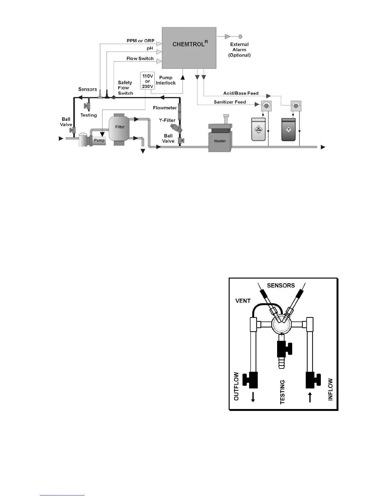
shown in Figure 4, it includes:
- two (2) compression gland fittings (1/2" MPT) for the
sensors,
- two (2) PVC tees (1/2" SST),
- one (1) in-line Y-filter (3/4" MPT),
- one (1) in-line flowmeter (1/2" FPT),
- a rotary safety flow switch (1/2" FPT),
- two (2) ball valves (1/2" SxS) for flow adjustment and for
isolating the bypass line during backwashing of the filter and
other maintenance operations,
- one (1) labcock (1/2" SxS) for water sampling and testing.
The Bypass Line Assembly should be installed exactly as shown
on Figure 4. In particular, make sure to install the flowmeter in a
vertical position and to install the flow switch downstream of
(after) the sensors to assure a smooth flow of water near the
sensors.
SENSOR CELL
For additional ease of installation and maintenance, it is also
recommended to mount the sensors in the optional Flow Cell,
Assembly as shown in Figure 5. It includes:
• the sensor cell with air vent and clear cover,
• two (2) compression fittings for the sensors,
• one (1) water sampling tap
• two (2) ball valves for controlling the water flow in and out.
WATER FLOW
Proper flow of water past the sensors is essential to obtaining
good readings.
To ensure proper water flow, make sure that the bypass line is
properly connected. As shown in Figure 4, the intake side should
be on the effluent side of the recirculation system, i.e. after the
filter. The return side should be to a low-pressure area - such as
the vacuum side before the recirculation pump, or downstream
after the heater, or atmospheric pressure in the pit of a vacuum
sand filter or balancing tank.
To check the water flow in the bypass line, start the main
recirculation pump. Open both the intake and the return valves
on the bypass line and read the flow rate on the flowmeter. It
should be in the middle of the range, i.e. about 2-3 gpm (about 8
to 12 l/min). If the water flow is too high, you can turn down the
valve on the RETURN SIDE of the bypass line. If there is no
water flow, replumb the bypass line as shown on the schematic.
NOTE: Most common installation problems with bypass line
installations are caused by faulty hydraulics.
Figure 4 – Installation with Bypass Line Assembly
Figure 5 - Flow Cell Assembly


 To Next Page